


Installation Manual ID RWA12.ABC-A / -B
FEIG ELECTRONIC GmbH
Page 23 of 28
E N G L I S H
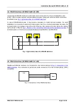
4.4 RS485 Interface (ID RWA12.ABC-B /-BK)
Connecting the RS485 interface is performed via the connector X1 at the terminals [R/A-] and
[T/B+]. The bus mode requires a superordinate computer (Host) with terminal resistor and active
termination (see
Fig. 3: typical structure of an RS485 data bus
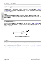
In case of RS485-data buses, it may become necessary to install terminal resistors. For each
installation, the necessity to install a terminal resistor has to be checked individually. Normally, the
terminal resistor is necessary only at the end of the bus, that means at the last device. By pinning
up the jumper J150 (see
Fig. 1: Position of the connecting terminals and the operational control
terminal resistor of 100
Ω
can be activated between lines RS485-A and RS485-B.
Host
Reader 1
J150
Reader 2
J150
Reader n
J150
Fig. 3: typical structure of an RS485 data bus
4.5 RS232 Interface (ID RWA12.ABC-A /-AK)
Readers with RS232 interface are connected to the host according to
. The connection is performed via the connector X1 at the terminals [R/A-], [T/B+]
and [GND].
Host
R/A-
T/B+
Reader
GND
GND
RxD
TxD
Fig. 4: Connection of the RS232-interface