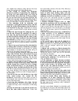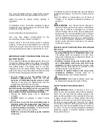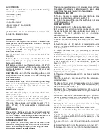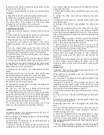
ACCESSORIES
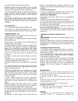
The Compound Mitre Saw is supplied with the following
accessories as standard:
• Saw blade (fitted)
• 6mm hex key
• Dust bag
• Instruction manual
• Battery capacity:
4Ah Li-ion (#)
• Charger (#)
(#) Not all the accessories illustrated or described are
included in standard delivery.
TRANSPORTATION
Lift the mitre saw only when the saw arm is locked in the
down position, the saw is switched off and the battery is
removed from the power tool.
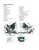
Only lift the saw by the operating handle (5) or outer
castings. Do not lift the saw using the guards.
BENCH MOUNTING
The saw base has holes in each corner to facilitate bench
mounting.
1.
Place the saw on a level, horizontal bench or work
table using bolts (not supplied) and fix the saw to the
bench using 4 bolts.
2.
If desired, you can mount the saw to a piece of 1/2” (13
mm) or thicker plywood which can then be clamped to
your work support or moved to other job sites and
re-clamped.
CAUTION.
Make sure that the mounting surface is not
warped as an uneven surface can cause binding and
inaccurate sawing.
RELEASE KNOB
The release knob (4) is provided for holding the cutting
head down while transporting or storing the mitre saw.
The saw must never be used with the release knob
locking the head down.
MITRE TABLE LOCKS
The mitre table locks (20) are used to lock the table at the
desired mitre angle.
The mitre saw cuts from 0° to 45° both left and right. To
adjust the mitre angle loosen the mitre table locks(20)(21)
and rotate the mitre table to the desired position.
The mitre table features positive click stops at 0°, 15°,
22.5°, 30° and 45° for quick setting of common mitre
angles.
BEVEL LOCK
The bevel lock (12) is used to set the blade at the desired
bevel angle. The mitre saw bevel cuts from 0° to 45° to
the left. To adjust the bevel angle loosen the bevel lock
and adjust the saw arm to the desired bevel angle.
SPINDLE LOCK BUTTON
The spindle lock button (22) prevents the blade in the
saw from rotating. Depress and hold the spindle lock
button while installing, changing, or removing the blade.
ROTATING LOWER BLADE GUARD
The rotating lower blade guard (8) provides protection from
both sides of the blade. It retracts over the upper blade
guard (6) as the saw is lowered into the workpiece.
TURNING ON AND OFF
1.
To turn the saw on press switch lock (34) to left and
depress and hold the on/off trigger switch (19)
2.
To turn the saw off release the switch lock (34) and
on/off trigger switch (19).
DUST EXTRACTION
1.
Fit the dust bag (11) to the dust extraction port.
2.
A vacuum dust extraction device can be connected to
the dust extraction port. Use a suitable
vacuum adapt or if
necessary. The dust extraction port has an internal
diameter of 40 mm.
SETTING THE TABLE SQUARE WITH THE BLADE
1.
Make sure that the battery is removed from the power
point.
2.
Push the saw arm (3) down to its lowest position and
engage the release knob (4) to hold the saw arm in the
transport position.
3.
Loosen the mitre locks (20) and lifting up the mitre
latch(21) .
4.
Rotate the table (16) until the pointer is positioned at 0°.
5.
Release mitre latch(21) and tighten the mitre locks (20).
6.
Loosen the bevel lock (12) and set the saw arm (3) at
0°bevel (the blade at 90°to the mitre table). Tighten the
bevel lock (12).
7.
Place a set square against the table (16) and the flat part
of the blade.
8.
Rotate the blade by hand and check the blade-to-table
alignment at several points.
9.
The edge of the set square and the saw blade should be
parallel.
10.
If the saw blade angles away from the set square,
adjust as follows.
11.
Use an 10 mm wrench or adjustable wrench to loosen
the lock nut securing the 0° bevel adjustment screw (29).
Also, loosen the bevel lock (12).
12.
Adjust the 0° bevel adjustment screw (29) using a 4
mm hex key to bring the saw blade into alignment with the
square.
13.
Loosen the Phillips head screw holding the pointer of
the bevel scale (13) and adjust the position of the pointer
so that it accurately indicates zero on the scale. Retighten
the screw.
14.
Retighten the bevel lock (12) and the lock nut securing
the 0° bevel adjustment screw (29).
SETTING THE FENCE SQUARE WITH THE TABLE
1.
Make sure that the battery is removed from the power
point.
2.
Push the saw arm (3) down to its lowest position and
engage the release knob (4) to hold the saw arm in the
transport position.
3.
Loosen the mitre locks (20) and lifting up the mitre latch
(21).
4.
Rotate the table (16) until the pointer is positioned at 0°.
5.
Release mitre latch (21) and tighten the mitre locks (20).


