V. MAINTENANCE.
Crazing (cracking) of lenses will cause reduced ef-
fectiveness of the light. Do not use cleaning agents
(which will cause crazing) such as strong deter-
gents, solvents, or petroleum products. If crazing of
lenses does occur, reliability of light for emergency
signaling purposes may be reduced until lenses are
replaced.
High voltages are present inside the lightbar. Wait
at least 10 minutes after shutting off the power
before servicing the unit. Disconnect ALL power to
the lightbar before any maintenance is performed.
Failure to do so may result in property damage,
serious injury, or death to you or others.
After prolonged operation, The unit gets hot and
can cause burns. Do not touch the unit while or
shortly after it has been operating. Always allow
the unit to cool before handling.
A.
General
.
Ordinary cleaning of the plastic lenses can be
accomplished by using mild soap and a soft rag. Should fine
scratches or a haze appear on the lens, they can be removed
with a specialty plastic cleaner/polish such as Plexus® and
a soft cloth. Alternatively, non-abrasive, high-quality, one-
step, automotive past cleaner/wax may be used.
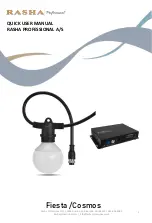
B.
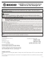
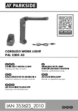
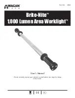
Outer Lens Removal (see figure 5).
Remove the end dome, then starting at one end,
pop the bottom of the lens off the lower extrusion. The
preffered method is to apply pressure to the center of the
lens with the thumb of one hand while the fingers of that
hand snap the lens from the extrusion. Alternatively, a
small, flat-bladed screwdriver may be used to carefully pry
the lens from the extrusion, ensuring that the lens and the
underlying o-ring cord are not damaged. Once the end is
free, the lens can be peeled off the bar. To install the lens,
hook the upper edge into its o-ring groove then snap the
lower edge into position. Seal the end of the lens/extrusion
joint with RTV as shown.
C.
End Dome Removal and Lamp Service.
1. Removal.
Remove the two 1/4-20 Phillips Flathead
screws retaining the dome assembly. Slide the assembly
away from the bar and unplug the 15-pin electrical
-6-
Figure 5.
connector. With the end dome removed from the bar,
remove the 10-32 Phillips head screw from the bottom of
the dome. The lighting units, upper plate, and lower plate
are now removed from the dome as an assembly. Once free
of the dome, the top plate and lighting units lift free from
the lower plate.
2. Installation.
Installation is reverse of disassembly. Inspect
the dome seal for cuts or tears, replacing as necessary
(see paragraph VI. Replacement Parts). Inspect the self-
clinching nuts in the bottom plate to verify that they
are not loose in the plate and that the threads are not
damaged. If either of these conditions exist, replace the
bottom plate assembly (see paragraph VI. Replacement
Parts). When installing the lighting units, pay attention to
the locating slots, tabs, and bosses. The 10-32 Phillips screw
and the two 1/4-20 Phillips flat head screws are coated at
the factory with anti-seize compound to prevent stainless
galling. If the screws are cleaned or replaced apply a
tiny amount of anti-seize (user-supplied – Bostik Never-
Seez© Is a commonly available brand) to the first two or
three threads. Before securing the Phillips head screw
in the bottom of the dome, ensure the holes for the dome
mounting screws are properly aligned in the dome, top
plate, and bottom plate. The dome seal must be compressed
to provide a good seal, thus pressure must be applied
to the dome during installation. A 1/4" drift punch (or a
1/4" shank of a #2 Phillips screwdriver) is used to align
the holes in the dome, top plate, end bracket, and bottom
plate. While keeping slight pressure inward on the dome,
align both holes, leaving the drift in the second hole while
screwing the screw in the first hole. Use due care when
staring the screws to prevent cross-threading. Start both
screws before securing either. Do not over tighten.
RTV
TOP VIEW
290A5636B
HOLLOW “O” RING
CORD
RTV
LENS
SOLID “O” RING
CORD
END VIEW