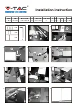
background image

Figure 1.

appropriate electrical connections. Ensure that the lines 

are adequately fused as shown and that the switch capacity 

is adequate for the current requirement.

Reverse polarity may damage any power supply 

and prevent operation. Ensure that the correct po-

larity is observed. The positive (+) power lead must 

be fused at the source for 40 amps.


3.  Connect the separate 10 gauge black lead to 

the vehicle ground terminal (-) and separate 10 gauge red 

lead to the vehicle battery hot terminal (+).

NOTE

All the lightbar functions can be activated by 

applying 12VDC to the appropriate control line. 

The 10 gauge black and red power leads must be 

connected to their respective battery terminals for 

a function check.


B. 

Function Activation – Excluding SignalMaster™


(see figure1).


1.  Mode Inputs.


There are three modes of operation available. 

Mode 1 (RED), Mode 2 (ORANGE), and Mode 3 (YELLOW) 

each have ten unique programmable flash patterns. One 

of the ten available flash patterns can be programmed to 

each mode input. Programming will be covered later in this 

section. To activate a mode, apply 12VDC to a mode input 

wire.


2.  Front-light Cut Off.


Applying 12VDC to the front-light cut off 

(GREEN) wire will cause the front of the lightbar to cut off. 

When the front-light cut off is active, only the rear and rear 

portion of the end cap will function.


3.  Rear-light Cut Off.


Applying 12VDC to the rear-light cut off 

(GREY) wire will cause the rear of the lightbar to cut off. 

When the rear-light cut off is active, only the front and 

front portion of the end cap will function.


4.  Work Lights.


Applying 12VDC to the Work lights (BROWN) 

wire will cause the Work lights to illuminate.


5.  Right Alley.


Applying 12VDC to the Right Alley (BLUE) 

wire will cause the Right Alley lights to illuminate.


6.  Left Alley.


Applying 12VDC to the Left Alley (VIOLET) 

wire will cause the Left Alley lights to illuminate.


7.  Mode Programming.


Each of the modes of operation can be 

programmed to operate with one of the available flash 

patterns listed below (see figure 2).

Mode 1 (Stand By Mode)


1 - Alternate Single Flash D1, D2, & S1 with P1, P2, &


S8


2 - Alternate Single Flash S1, S2 with S7, S8


3 - Alternate Double Flash S1, S2, S7, S8 with S3, S4,


S5, S6


4 - Alternate Double Flash S1, S2, S7, S8 with S3, S4,


S5, S6, P1, P2, D1, D2


5 - Alternate Double Flash S1, S2, S7, S8 with S3, S4,


S5, S6


6 - Alternate Double Flash D1, D2, P1, P2 with S3, S4,


S5, S6


7 - Alternate Double Flash D1, D2, P1, P2 with S3, S4,


S5, S6 followed by Alternate Double Flash S1, S2,


S7, S8 with S3, S4, S5, S6, P1, P2, D1, D2


8 – Wrap-Around Inside to Outside 


9 – Wrap-Around Inside to Outside to Inside followed


by Wig/Wag Alternate Flash


10 -Alternate Full Flash - S1, S3, S6, S8, D2, D4, D5,


D6, D7, D8, P2, P4, P5, P6, P7, P8 with S2, S4, S5,


S7, D1, D3, P1, P3

-2-

Figure 2.

290A5632

RED

1 A

1 A

1 A

1 A

1 A

1 A

1 A

1 A

1 A

1 A

MODE 1

ORANGE

MODE 2

YELLOW   

MODE 3

GREEN

FRONT LIGHT CUT-OFF

GREY

REAR LIGHT CUT-OFF

BROWN

WORKLIGHTS

VIOLET

LEFT ALLEY

BLUE

RIGHT ALLEY

BEIGE

SIGNALMASTER RIGHT

WHITE

SIGNALMASTER LEFT

1 A

1 A

BLACK

SIGNALMASTER CENTER-OUT 

PINK

PROGRAM

RED

LOW POWER

GREEN

PASSENGER-SIDE HIGH POWER

WHITE

DRIVER-SIDE HIGH POWER

BLACK

GROUND

(+) BATTERY

(-) BATTERY

CONTROL CABLE

(+) POWER/IGN
(+) BATTERY
(-) BATTERY

12 COND 22 AWG CABLE

4 COND 18 AWG CABLE

40 A

STOP/TAIL/TURN CABLE

S/T/T

S/T/T

WK

LGT

WK

LGT

D1

D2

D3

D4

D5

D6

P1

P2

P3

P4

P5

P6

S2

S1

S3

S4

S6

S7

S8

QUADRANT A

QUADRANT B

QUADRANT C

QUADRANT D

290A5633

Summary of Contents for RAYDIAN

Page 1: ...sult in property damage serious injury or death to you or others I GENERAL HEAVY OBJECT Get assistance when lifting or installing Failure to do so will cause permanent bodily injury The Raydian is a LED light bar with supplemental white halogen area lighting designed for use with Federal Signal lightbar controllers and or single switches rated at 2 amperes and above The base is a two piece extrude...

Page 2: ... to the Work lights BROWN wire will cause the Work lights to illuminate 5 Right Alley Applying 12VDC to the Right Alley BLUE wire will cause the Right Alley lights to illuminate 6 Left Alley Applying 12VDC to the Left Alley VIOLET wire will cause the Left Alley lights to illuminate 7 Mode Programming Each of the modes of operation can be programmed to operate with one of the available flash patter...

Page 3: ...ntire bar twice followed by a Wrap Around Inside to Outside followed by an Alternate Double Flash followed by a Wrap Around Inside to Outside Programming is accomplished as follows a Apply 12VDC to the mode input to be programmed The bar will flash the current pattern b Momentarily apply 12VDC to the Program PINK wire The lightbar will stop briefly then the entire lightbar LEDs will flash the numb...

Page 4: ...ent pattern b Momentarily apply 12VDC to the Program PINK wire The SignalMaster will then begin to flash the newly selected pattern c Repeat step b until the desired pattern is selected d To program the other modes apply 12VDC to the desire mode input and repeat steps b and c 4 D SignalMaster Control Head Installation When installing equipment inside air bag equipped vehicles the installer MUST en...

Page 5: ...stare into the light beam at close range After installation check the entire system to be sure the lights are flashing properly and all light system functions are operating properly SAFETY MESSAGE TO OPERATORS People s lives depend on your safe use of our products Listed below are some important safety instructions and precautions you should follow Although your warning system is operat ing proper...

Page 6: ...ice 1 Removal Remove the two 1 4 20 Phillips Flathead screws retaining the dome assembly Slide the assembly away from the bar and unplug the 15 pin electrical 6 Figure 5 connector With the end dome removed from the bar remove the 10 32 Phillips head screw from the bottom of the dome The lighting units upper plate and lower plate are now removed from the dome as an assembly Once free of the dome th...

Page 7: ... Solaris LEDs see figure 7 1 Remove the 6 Phillips head screw retaining the PCB assembly 2 Slide the PCB assembly up then away from the reflector to disengage the pins from the LED 3 Assembly is the reverse of disassembly Prior to installation of the PCB assembly ensure that the LED connector pins on the PCB are not bent or damaged Figure 6 Figure 7 H LED Module Replacement Solaris LEDs see figure...

Page 8: ...mblies PCB Assembly Backer Board 2005340 PCB Assembly STT Backer Board 2005314 Reflector Assembly 6 Button Amber 8654167 02 Reflector Assy Stop Tail Turn Red 8654207 LED 6 Button Amber 8625234 A LED STT Red 2005303A Copyright 2006 Federal Signal Corporation 8 290A5639 1 4 FLAT WASHER END BRACKET ASSEMBLY P C B BOARD AND BRACKET ASSEMBLY EXTRUSION 1 4 LOCKWASHER 1 4 20 HEX HEAD SCREW DOME SEAL ...

Reviews: