background image

25500525

Rev. A0 0619

Printed in U.S.A.

© Copyright 2019 Federal Signal Corporation
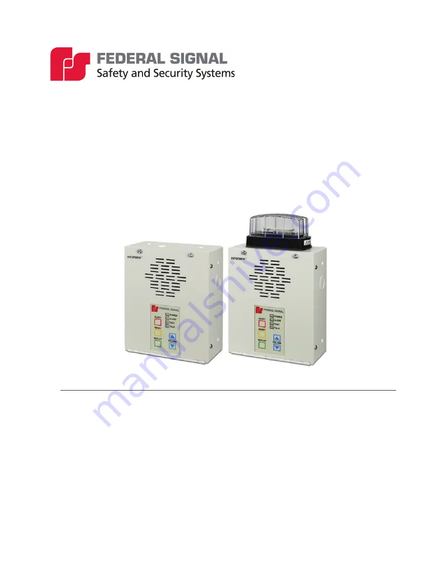
Informer-IP

 Wall Mount 

Model I-IPW Series B

Two-Way IP-enabled Intercom and Alarm Initiation Point 

Strobe is optional.  

(Version 3.2.0.1 and later)

Description, Specifications,  

Installation, and Operation Manual 

Summary of Contents for Informer-IP Wall Mount B Series

Page 1: ...right 2019 Federal Signal Corporation Informer IP Wall Mount Model I IPW Series B Two Way IP enabled Intercom and Alarm Initiation Point Strobe is optional Version 3 2 0 1 and later Description Specif...

Page 2: ...nty is in lieu of all other warranties express or implied contractual or statutory including but not limited to the warranty of merchantability warranty of fitness for a particular purpose and any war...

Page 3: ...Installation 10 Determine a Suitable Location 10 Wall Mounting 11 Recessed Mounting 12 Wiring the Device 13 Memory Card Removal and Installation 15 Testing and Training 15 Operations 15 Controls 16 V...

Page 4: ...Table 9 RS232 Connector Pin out 18 Table 10 J2 Input Power from transformer 19 Table 11 JP3 on the main PCB Microphone Enable Jumper 19 Table 12 Replacement Part Numbers 19 Figures Figure 1 Informer I...

Page 5: ...y to confirm that it will be operational in an emergency Safety Messages to Installers People s lives depend on your safe installation of our products It is important to follow all instructions shippe...

Page 6: ...ctions to refer to the system may not provide the intended audible warning and service personnel may be exposed to death permanent hearing loss or other bodily injury File these instructions in a safe...

Page 7: ...trobe Using existing network infrastructure significantly lowers installation costs and simplifies wide scale deployments The Informer IP provides an unmatched value for two way indoor alert and notif...

Page 8: ...B Informer IP requires Federal Signal Commander application software There is a programming fee associated with Informer IPs programmed at the factory Contact your local representative for a quotatio...

Page 9: ...2014 mode B units shipped after February 2014 mode A Standby 60 mA With siren or message audio 110 mA Audio Data Playback Storage 17 hours and 4 000 messages with 2 G microSD card Audio Frequency res...

Page 10: ...r that it is connected to Agency Compliance Complies with UL 60065 and C22 2 No 60065 Installation Read and adhere to all safety warnings in this manual before installing the Informer IP To prevent in...

Page 11: ...as eight holes two sets of four located on the back of the unit that accepts 8 screws Mounting location determines which set of four holes are used Exterior wiring can enter the Informer IP through an...

Page 12: ...re placed into material that can adequately support the weight of the Informer IP Figure 4 Side View Hole Measurements To recess mount do the following 1 Cut a hole that is 8 25 x 7 25 x 3 inches H x...

Page 13: ...and components 5 Connect the wires to the terminal block by inserting the stripped ends of the wires into the connectors as far as they can travel Connect the earth ground to the terminal block posit...

Page 14: ...3 C33 R23 C35 C6 C68 C73 C67 R41 C99 R80 C129 R149 J3 C83 JP5 TP2 C27 C7 C38 R2 R26 C43 R85 C24 R7 R4 D3 D18 C82 C76 D14 JP7 C74 R47 U19 C94 R77 JP9 R84 D6 C42 C45 C13 C11 C14 R18 R17 U18 C80 R50 R51...

Page 15: ...the following Test the Informer IP and all accessories from the control point s to ensure it is operating properly Ensure all users are properly trained to use the system before putting the Informer...

Page 16: ...t and Talk LEDs Scrolling Message Display Relay Outputs REPLAY The REPLAY button replays last voice message received if the red alert light is blinking If the Alert light is not blinking the event has...

Page 17: ...Intercom chat session ends when the control point Ends the Call or Resets the device The following indicators are for troubleshooting purposes only These indicators are not visible when the unit is c...

Page 18: ...lly closed relay 1 5 Common relay 1 6 Normally open relay 1 7 600 ohms audio output 8 600 ohms audio output Alert Rear Input Located on the inside of the Informer IP Wall Mount housing is a two positi...

Page 19: ...on the PCB is JP3 which normally has a shorting plug to enable the built in microphone functionality Model I IPW Series B of the Informer series uses the speaker as the microphone Table 11 JP3 on the...

Page 20: ...34 3400 extension 7511 or Technical Support at 800 524 3021 or 708 534 3400 extension 7329 or through e mail at techsupport fedsig com For instruction manuals and information on related products visit...

Reviews: