FEC Remote Lighting Controller V4 HP0832
User Installation and Operation Manual
© Interleader Ltd 2020
45 of 64
26/08/2020
9.9 Mains wiring
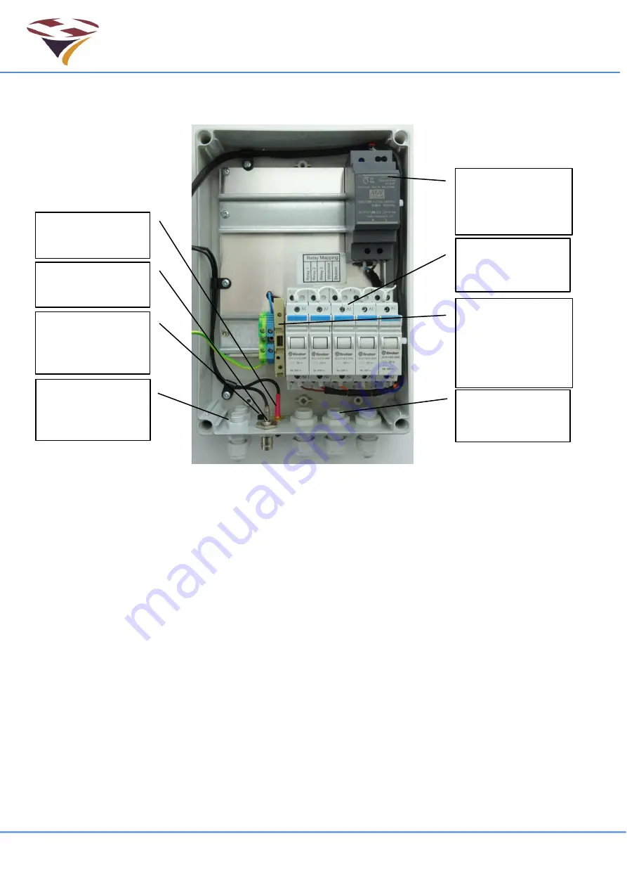
The arrangement of the base units is shown below:
Notes:
1) Live (Brown), Neutral (Blue) and Earth (Green/Yellow) 4mm IMO DIN rail mounted
connector strips are provided for customer wiring.
2) Additional connectors can be added by the customer but pay particular attention to:
a. Such connectors are often open on one side. Care must be taken to ensure that the
open side is always covered by its neighbour or end plate.
b. The earth connector is fixed and grounded to the DIN rail by a central screw. To
move this connector, slacken the central screw, move as required and re-tighten.
c. The Earth connector provides the earth bonding connection to the controller.
d. The connectors must be gently pushed tight against the PSU and Relay Interface
Board to ensure that these items are prevented from sliding on the rail.
3) The controller is fitted with a mains powered 12V Power Supply Unit (PSU). The installer
must connect this to the incoming mains supply via the fuse (provided) using suitable 2 core
cable (2x1mm 240V). The PSU is double insulated and is not earthed.
4) The relays are rated at 20A AC for a resistive load.
5) If higher currents or highly inductive loads are to be switched by the controller the use of an
exte
rnal ‘Contactor’ of the correct rating must be used.
DIN Rail mounted
connector strips.
Customers may
add additional
items
12V DC 30W
Mains PSU
100-240VAC
meteorological
and Aux
connectors
Position of
optional UHF
connector
VHF BNC
connector
3 Mains In/Out
cable glands
5 off 20A Relays:
1NO
Cellular Radio
connector
Summary of Contents for HP0832
Page 64: ...End of Document...


