Febco 856 Maintenance Manual Download Page 5

5

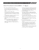
1 .   FEBCO backflow prevention assemblies can be serviced with standard 

tools and are designed for ease of maintenance . The assemblies are 

designed to be serviced in line, so the unit should not need to be 

removed from the line during servicing . NO special tools are required .

2 .   The most common cause of check fouling is dirt and debris in the 

seating areas . The line should be flushed clean of debris before instal-

lation of the assembly . To flush the line after installation of the assem-

bly, slowly close the inlet shutoff valve, remove the covers and spring 

assemblies of both check valves and open the inlet shutoff valve to 

allow sufficient flow of water through the assembly to clear all sand, 

debris, etc . from the line . If debris in the water continues to cause 

fouling, a strainer may be installed upstream of the assembly (check 

local codes) .

3 .   Rinse all parts with clean water before reassembly .
4 .   Lubricant is recommended only for #2 check cover O-ring to help hold 

O-ring in place during reassembly (Series 870V and 876V) . Apply a thin 

coating of the lubricant supplied in the repair kit to the O-ring groove in 

the #2 check body, and position the O-ring in the groove . 

5 .   Carefully inspect seals and seating surfaces for damage or debris . If 

the check valve seat disc has been severely cut at the seat ring diam-

eter, the assembly has been subjected to extremely high and repeated 

back pressure . Either thermal water expansion or water hammer are 

the most likely causes . If back pressure persists, consider installation 

of a pressure relief valve downstream of the assembly .

6 .   Use caution to avoid damaging any guiding surfaces while handling 

parts . Do not force parts together . The O-ring seals used in FEBCO 

assemblies require only a small tightening force to insure a 

positive seal .

7 .   Test unit after servicing in accordance with locally approved test 

methods to insure proper operation (See Page 5 for more details) .

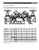
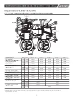
8 .   Refer to applicable parts lists and cut-a-ways (Pages 11-13) 

for visual aid information .

MAINTENANCE MANUAL SERIES 850, 856, 870V & 876V 2

1

2

"- 10" (65 – 250mm)

General Service Procedures 

1

2

" - 10" (15-250mm)

Summary of Contents for 856

Page 1: ...ing this equipment Table of Contents Features and Operating Procedures 2 How to Order Parts 2 Trouble Shooting Guide 3 Vandalism 3 Testing 3 Freeze Protection Procedures 4 General Service Procedures 4...

Page 2: ...led in the vertical orientation must include vertical support under the second check body section Double Check Detector Assemblies Bypass Operation All low flow demands up to a minimum of three GPM ar...

Page 3: ...rrectly The assembly should be tested at time of ini tial installation after servicing or maintenance and at least annually there after Acceptable test procedures are published by Foundation for Cross...

Page 4: ...check module until all water inside valve drains back out through inlet drain 7 If you blowout the piping downstream of the backflow assembly using compressed air Connect the air supply to the outlet...

Page 5: ...g to help hold O ring in place during reassembly Series 870V and 876V Apply a thin coating of the lubricant supplied in the repair kit to the O ring groove in the 2 check body and position the O ring...

Page 6: ...eck disc stem threads Lift the arm and remove the check disc Item 6 Inspect sealing surface for debris or damage Replace check disc if necessary NOTE When jam nut Item 16 is tight check disc is design...

Page 7: ...7 905158 905159 905160 Items 3 3 1 3 2 3 4 4 4 1 4 2 5 RUBBER PARTS KIT ALL Part 905249 905163 905164 905165 Items 2 1 3 1 6 15 26 35 35 1 45 45 1 COVER ASSEMBLY With Bulkhead Part 905167 905168 90516...

Page 8: ...26 35 35 1 45 45 1 COVER ASSEMBLY Inlet Check ALL Part 905167 905168 905169 905170 905171 Items 2 2 1 15 COVER ASSEMBLY Outlet Check ALL Part 905244 905245 905246 905247 905248 Items 2 2 1 15 BULKHEA...

Page 9: ...ammer or other causes of excessive water pressure Seat discs damaged in such a manner should be replaced and not turned over to be reused 3 Check Seat Ring Replacement a The seat rings are threaded in...

Page 10: ...Nitrile 11 Washer Stainless Steel 12 Screw Stainless Steel 13 Spring Stainless Steel 30 Test Cock Bronze 35 Seat Ring Bronze 36 O ring Buna N 40 Ball Valve Bronze 40 1 Ball Valve Bronze 40 2 Ball Val...

Page 11: ...ead loss Cast ductile iron bodies for lighter weight Lowest installed cost Saves on labor and material Choice of cost saving N Shape designs revolutionary vertical designs or conventional in line desi...

Page 12: ...e sole and exclusive remedy for breach of warranty and the Company shall not be responsible for any incidental special or consequential damages including without limitation lost profits or the cost of...

Reviews: