


4
MAINTENANCE MANUAL SERIES 850, 856, 870V & 876V 2
1
⁄
2
"- 10" (65 – 250mm)
Freeze Protection
The Double Check Backflow Prevention Assembly may be subject to
damage if the internal water is allowed to freeze . The unit must be pro-
tected from freezing using a heated enclosure, insulation using heat tape,
or other suitable means . The unit must always be accessible for testing
and maintenance . If the system will be shut down during freezing weath-
er, use the following procedures to drain internal passages .
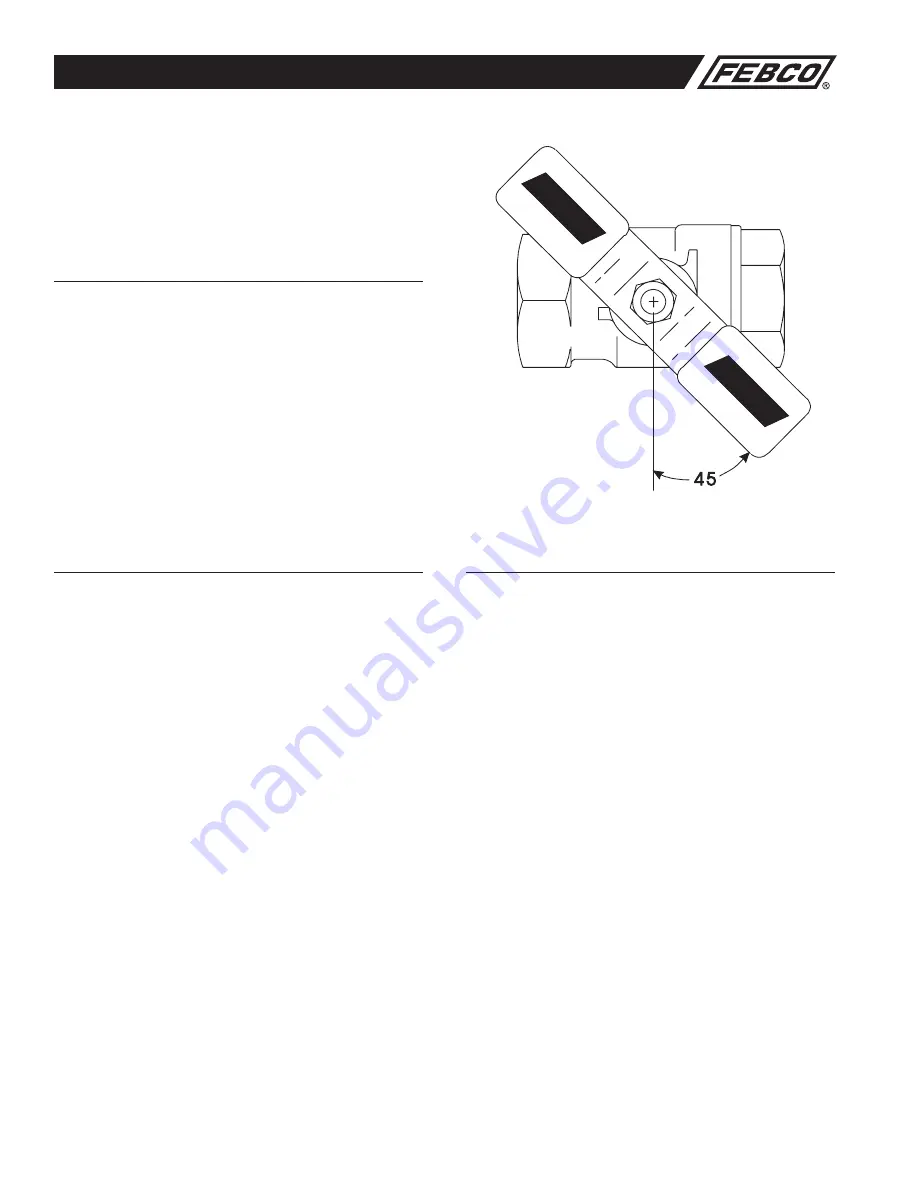
Ball Valve Shutoff Draining Procedure
If the assembly has been installed with ball valve shutoff valves, they
must also be properly drained to prevent freeze damage . After draining
procedure has been completed on the backflow prevention assembly,
position all ball valve shutoffs and test cocks in a half open/half closed
(45 degree) position .
Open the ball valve approximately 45 degrees while draining the pipeline
and assembly to allow water between the ball valve and valve body
to drain . Leave the ball valve in this position for the winter to prevent
freeze damage .
The ball valve must be fully closed before the system is repressurized .
OPEN AND CLOSE BALL VALVES SLOWLY TO PREVENT DAMAGE
TO THE SYSTEM CAUSED BY WATER HAMMER.
Main Valve Draining Procedure
1
⁄
2
"-2" (15-50mm)
1 . Close the main shutoff valve .
2 . Open the inlet drain .
3 . Open the inlet and outlet ball valves 45 degree (half open, half closed) .
4 . Open all testcocks .
5 . Open the outlet drain .
6 . Remove the cover and inlet check module until all water inside valve
drains back out through inlet drain .
7 . If you “blowout” the piping downstream of the backflow assembly
using compressed air:
Connect the air supply to the outlet drain and close the outlet ball valve .
After clearing the system with air, partially open the outlet ball valve .
Leave all drain valves, testcocks, and ball valves in half open/half closed
position for the winter . (See above for more detailed instructions) .
Main Valve Draining Procedure
2
1
⁄
2
" - 10" (65-250mm)
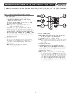
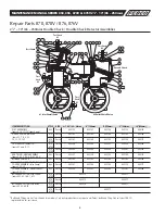
Slowly close supply valve within freeze protected area, open all test
valves on the backflow preventer . For sizes 2
1
⁄
2
" - 10" (65-250mm), water
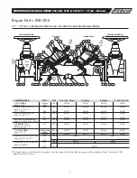
within the zone between the two checks may be drained by loosening
the bolts (Item 24) on the bottom cover plate (Item 19) . (See Page 8) .
All water will be drained from the inlet side and the zone between the
two checks of the Series 870V . All water on the inlet side will be drained
down to the No . 1 test cock on the Series 850 . The remaining water on
the inlet side may be drained to the lowest point on the Series 850 2
1
⁄
2
"
- 10"
(65-250mm) by removing the small (Item 36) bottom plate . (See Page 8) .
If you desire to add a drain plug, there is sufficient material for drilling and
tapping
1
⁄
4
" IPS thread in the cover (Item 19); however, adding a drain plug
is not necessary . Loosen the mounting nuts and bolt to allow drainage
from beneath the plate .
The system design must provide a means for draining upstream of the #1
shutoff valve and downstream of the #2 shutoff valve .
Position the assembly shutoff valves and test cocks in the half open/half
closed position to allow complete draining of the assembly shutoff valve
bodies and test cocks . (See above) .