background image

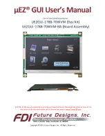
µEZ® GUI User

s Manual 


Covers the following products: 

UEZGUI-1788-70WVM (Dev Kit) 

UEZGUI-1788-70WVM-BA (Board Assembly)


NOTICE: At FDI we are constantly improving our documentation. Please get the latest version of this 

document in the documentation tab of the product page at www.TeamFDI.com 


Copyright ©2016, Future Designs, Inc., All Rights Reserved 

Example Display Images 

shown for Reference Only 

Summary of Contents for uEZ GUI

Page 1: ...VM BA Board Assembly NOTICE At FDI we are constantly improving our documentation Please get the latest version of this document in the documentation tab of the product page at www TeamFDI com Copyrigh...

Page 2: ...___________________________________________________ 10 12 Software _____________________________________________________________ 11 13 Configuring Rowley CrossWorks CrossStudio for ARM for J Link Flas...

Page 3: ...Temperature Range ____________________________________________________ 26 21 ESD Warning __________________________________________________________ 26 22 Real Time Clock Backup Time___________________...

Page 4: ...c or mechanical for any purpose without the express written permission of Future Designs Inc 996 A Cleaner Way Huntsville AL 35805 For more information on FDI or our products please visit www teamfdi...

Page 5: ...directly into your product or FDI offers prepackaged versions FDI also offers low cost customization services for customer specific hardware software or packaging applications at volumes of 500 units...

Page 6: ...gger https www segger com cms jlink software html Rowley Crossworks IDE download for 30 day evaluation https www rowley co uk arm index htm 5 Functional Description LPC1788 120 MHz Cortex M3 based Mic...

Page 7: ...ctor labeled 5V 1A min input only Note that the other USB connector P1 is for communications only and will not supply power to the unit Also note that the minimum power requirement is 1 0A so most USB...

Page 8: ...l temperature at any time However it is only valid when an external temperature sensor has been connected to the EZ GUI hardware Digilent Inc sells a temperature sensor part number 410 287P that could...

Page 9: ...ecting the brightness icon shows a menu with color bars and a brightness adjustment slider Move the slider up or down to adjust the brightness Select Back to return to the Settings Menu Time Date Use...

Page 10: ...ed format with a resolution of 480 272 or greater Video Creation Guide https www teamfdi com public_html uez Video uEZ 20Auto 20Video 20Conversion 20Guide pdf 10 EZ Doxygen online HTML documentation E...

Page 11: ...maximizing software reuse The diagram below shows a typical embedded application stack EZ has three primary categories of components that help simplify embedded application development 1 Operating Sy...

Page 12: ...df 2 Plug in the J Link device into the PC and install any drivers as directed The Segger J Link drivers can be found at https www segger com cms jlink software html with additional information at htt...

Page 13: ...nfiguration for configuring the J Link tools To update IAR s J Link dll you just need to run Segger s J Link DLL Updated and select the IAR install you wish to update and click Ok 15 Configuring Keil...

Page 14: ...icroSD Looks for a Micro SD Card with the file SLIDES SLIDES TXT NOR Flash Memory test basic test is performed to confirm read write access RTC Sets the time and confirms the clock is running SDRAM si...

Page 15: ...ader This smaller connector provides 100 of the functionality of the standard 20 pin JTAG connector but utilizes 70 less board space The connector is a standard part available from most major vendors...

Page 16: ...ns Both of these adapters come with the required cable SEGGER 9 pin adapter https www segger com jlink adapters html CM_9pin OLIMEX 9 pin adapter https www olimex com Products ARM JTAG ARM JTAG 20 10...

Page 17: ...t on a PC the UEZGUI 1788 70WVM BA will appear as a USB Flash Drive to the PC allowing the user to read and write files directly to the MicroSD card The unit uses a MicroSD Socket for flexible mass st...

Page 18: ...nt damage to the socket that is not covered under warranty To insert the card just push it into the socket until a click sound is heard Start with the microSD card in this position relative to the mic...

Page 19: ...partially ejected from the socket Finally grab the card and gently pull to remove it See the following pictures for proper micro SD removal To remove the microSD card gently push it into the socket a...

Page 20: ...y 4 Ground 5 RXD 6 TXD J11 Alternate Power and communication The UEZGUI 1788 70WVM BA includes an alternate power and communication header This header provides access to UART 2 or I2C Channel 2 as wel...

Page 21: ...Supply This power supply is only included in the development kit and is not included with the UEZGUI 1788 70WVM BA Note that the other USB connector P1 is for communications only and will not supply p...

Page 22: ...ral purpose digital Input Output pin I O SSEL0 Slave Select for SP0 I O RXD1 Receiver input for UART1 I 9 P0 15_TXD1 1 P0 15 General purpose digital Input Output pin I O SCK0 Serial clock for SSP0 I O...

Page 23: ...3 3 V pin LOW on this pin indicates LPC1788 being in Reset state O 25 P0 26_AD03_AOUT_RXD3 1 P0 26 General purpose digital Input Output pin I AD0 3 A D converter 0 input 3 O AOUT D A converter output...

Page 24: ...4 UART4 Transmit data O 3 P5 3_RXD4_SCL0 LPC1788 only P5 3 General Purpose digital Input Output I O RXD4 UART4 receive data I SCL0 I2C Clock for FM Operation I O 4 P5 2_MAT3 2_SDA0 LPC1788 only P5 3 G...

Page 25: ...TP_RL_Y2 Touch panel interface right side horizontal Not Typically Supported P0 24 General Purpose digital Input Output I O AD0 1 A D converter0 input 1 I 19 TP_RL_X1_P0 23_AD0 0 TP_RL_X1 Touch Panel...

Page 26: ...he calculated backup time is shown below Super Capacitor Typical Voltage Stop Voltage Maximum Current Typical Backup Time XH414HG 3 0 V 2 0 V 1 A 18 hrs 23 Power Requirements Power is supplied into th...

Page 27: ...of providing a maximum of 100mA of 3 3V power for external use over the expansion connectors If more than 100mA of 3 3V is needed for an expansion board o Then the primary power input i e 5V should b...

Page 28: ...l P a g e 28 3 20 2024 Copyright 2024 Future Designs Inc Revision 5 24 Mechanical Details The following illustrations show the mechanical details of the UEZGUI 1788 70WVM BA PCB Figure 6 Mechanical La...

Page 29: ...UEZGUI 1788 70WVM User s Manual P a g e 29 3 20 2024 Copyright 2024 Future Designs Inc Revision 5 25 Dimension comparison between 70WVT and 70WVM models...

Page 30: ...UEZGUI 1788 70WVM User s Manual P a g e 30 3 20 2024 Copyright 2024 Future Designs Inc Revision 5...

Reviews: