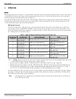
OPERATION
FS10 Series
32
Fluid Components International LLC
Fail-safe Position (Function 3)
This function establishes the state of the relay during normal operation and alarm condition. It is common to set the fail-safe so that the relay
is “energized” or activated under normal operating conditions. An alarm condition (switch point activated) results in the de-energized state.
That assures an alarm state if power is lost to the device as well.
If the relay is bypassed in favor of a solid-state binary output, set up the system so that a no-power condition results in an alarm state. Under
normal operating conditions, the transistor should be ON, resulting in an approximate 5 VDC signal to ground. Power loss or an alarm condi-
tion results in 0 VDC to ground.
Hysteresis (Function 8 and 9)
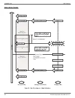
In the case of the flow switch, hysteresis is defined as the difference in signal level between turning on the relay and turning it off. If the
hysteresis is set to zero, that point is the same and can result in chattering, rapidly turning the relay on and off, in slow moving processes. A
hysteresis level is applied to minimize the possibility of chattering around the switch point. It is set as a percent of the established span.
The hysteresis is applied either above the switch point or below the switch point. For example, if hysteresis is set above the switch point in
an application requiring low flow detection, the relay changes state as the signal falls below the switch point. The relay, however, will not
reset until it reaches the switch point value plus the added hysteresis value. The default setting is hysteresis above the switch point and set
at 2% of the span value. If changes are required to the default, see how the hysteresis is applied in Function 8 and set the value in Function
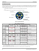
9. Any value hysteresis may be applied through the Windows PC interface (recommended) or the RS232 command line interface. The button
functions are limited to settings between 0% and 10% in 1% increments.
Time Delay (Function 10 or 11)
A time delay can be applied to the switch point in one of two ways, (a) The time delay is applied to activate (Function 10) the relay after the
switch point has been reached, or (b) The time delay is applied to de-activate (Function 11) the relay after the switch point has been reached.
The time starts as the switch point is reached and counts down as long as the switch point value is retained. The relay then changes state. If
the switch point was reached, but not maintained during this period, the time delay resets and the relay does not change state. The default
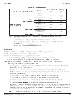
value is zero seconds and can be increased in 1-second increments up to 10 seconds with the buttons (time delays considerably higher are
achievable through the RS232 interface (>65,000 sec. with PC interface).
Function 10 operation (relay change of state is delayed this amount [sec.] after signal reaches switch point) is normally used in applications
where false trips may occur due to turbulent or cyclic flow action or in wet dry applications where splashing during vessel filling, for example,
may cause premature actuation. Proper setting of the time delay in this mode can be very effective in preventing problematic nuisance trips.
Function 11 operation (relay change of state is delayed this amount [sec] after signal leaves switch point) may also be used in cyclic flow con-
ditions. Another possible use may be to fill a vessel after a low level is reached. For example, the level reaches the low level switch point; the
relay immediately changes state and is set to actuate a solenoid valve that begins the filling action. A time delay may be set that corresponds
to the time needed to fill the vessel.
Note:
The time delay function is dependent on the Failsafe Position (Function 3). Therefore, select the proper mode of delay based
on relay being activated in normal operation and de-activated in the alarm condition. These selections are likely to be differ-
ent when alarm settings are for low flow (or dry) verses high flow (or wet) applications.
Alarm Simulation (Function 12)
This function is used to force the output to the highest or lowest value, resulting in a change of relay state as well. Alarm simulation may be
useful in testing the system in which the FS10 is installed.
Filter Setting (Function 14)
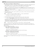
A filter is applied to the raw input signal (delta R). It is used to smooth the output against fluctuating or turbulent flow conditions. The range
of the filter setting is 3-100. The default setting is 18 and reduces the time response by < 2 seconds. A setting of 100 provides the maximum
dampening of the signal and decreases the response time approximately 10 seconds. Settings from 3 to 100 can be applied using the Win-
dows PC interface or the RS232 command line interface. The buttons permit changes of values 3, 18, 30, 50 and 100 only.

