52
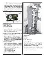
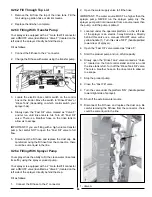
1 - Agitation Throttling Valve
If the sprayer has a self cleaning filter, the agitation throttling
valve will be the first valve located at the bottom of the valve
control center tower. See preceding page for location.
There are three agitation jets inside the product tank. Two
are located in the sump near the front of the tank and one is
located at the rear of the tank.
NOTE: If the sprayer is equipped with a self cleaning filter
the jet at the rear of the tank will be controlled by the self
cleaning filter. See the self cleaning filter section for details.
It is recommended that you have the agitation throttling
valve completely OPEN unless foaming occurs.
9.13 Standard Primary Filter
Your sprayer is equipped with a primary filtration system.
This filter could be in the form of a “Y” strainer (standard)
or a self cleaning filter (optional). The filter is located on the
right side of the sprayer under the sprayer platform. The
filter is installed on the pressure side of the pump and has
a 50 mesh screen. Other size mesh screens are available
through Fast Manufacturing, Inc.
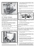
9.14 In Line Filter Kit
The in line filters are located on the mid section of the boom
and are attached to the ON/OFF valves. There will be one
filter per ON/OFF valve and are equipped with 50 mesh
screens. Optional size screens are available through your
Fast Manufacturing parts dealer.
^
WARNING
Wear protective clothing (such as goggles,
rubber or chemical resistant gloves and a
respirator) while handling or working with
chemicals. Keep protective clothing clean and
in good condition or discard.
To clean screens:
1. Use caution when removing filter canisters or boom
lines. There could be residual pressure in the filter or
boom lines.
2. Place a container under the filter canister.
3. SLOWLY loosen and remove the drain plug from the
bottom of the canister and let filter drain completely.
4.
Unscrew the filter canister, remove the screen and rinse
in clean water.
5. Wipe the inside of the canister with a clean rag.
6.
Lightly oil the O-rings on the filter canister and the drain
plug.
7. Reassemble the filter screen into the canister and the
canister to the filter head. DO NOT over tighten.
8. Reinstall the drain plug into the canister. DO NOT over
tighten.
9. Dispose of the waste material properly.
9.15 Self Cleaning Filter (Optional)
Refer to the “Maintenance” section of this manual for filter
maintenance interval and procedures.
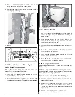
A self cleaning filter is an optional accessory. This filter has
a throttling valve located in the front left hand side of the
sprayer. A quick coupler system and hose is mounted to
the bottom of the filter cannister. The unmixed chemical that
does not go through the 50 mesh screen is returned to the
product tank through the rear agitation jets, reagitated and
sent back through the system.
•
The throttling valve should remain completely open for
the self cleaning filter to operate properly.
When the cannister is removed from the filter head, the
throttling valve MUST be closed.
To clean the filter screen:
^
DANGER
Agricultural chemicals are TOXIC, chemicals
not safely used, handled, stored and disposed
of can cause serious injury or death to
individuals or harm the environment.
Wear protective clothing and equipment.
Read, understand and follow the chemical
manufacturer’s label.
Contact your chemical supplier, county
extension agent or other qualified person if
you have questions on chemical usage.
1. Turn the product pump OFF.
Summary of Contents for BW750
Page 18: ...18...
Page 19: ...19 Decal A Decal B Decal C Decal D...
Page 20: ...20 Decal E Decal F Decal G Decal H Decal I Decal J...
Page 21: ...21 Decal K Decal L...
Page 36: ...36 9 6 Spray Tip Wear...
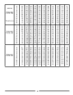
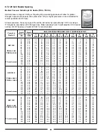
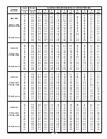
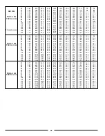
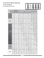
Page 43: ...43 9 8 TeeJet Air Induction Spray Tips 9 8 1 20 Inch Spacing At Various Speeds And Pressures...
Page 81: ...81 12 3 Raven Console Calibration Information...
Page 83: ...83 Notes...


