INSTRUCTION, USE
AND MAINTENANCE MANUAL
GB
Page 29 of 168
7522-M001-14_P
GG40256.11SL - GG40256.11ST - GG40256.15
GG40256T.15 - GG40256A.15 - GG40256D.15
GG40256TD.15 - GG40256.15SL - GG60360.15
GG60360T.15 - GG60360A.15 - GG60360D.15 - GG60360TD.15
12.6.2 Demounting
THROUGHOUT TYRE MOUNTING/
DEMOUNTING OPERATIONS,
CHECK THAT THE SELF-CEN-
TRING CHUCK CLAMPING PRES-
SURE IS CLOSE TO THE MAXIMUM
OPERATING VALUE (160 - 180
BAR).
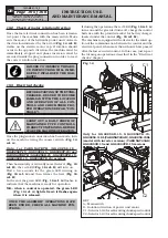
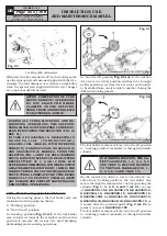
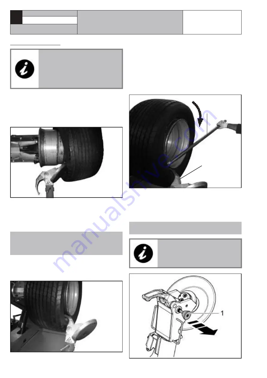
Tubeless tyres can be removed in two ways:
A.
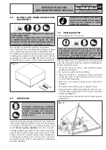
If the wheel does not present particular problems,
continuing beading operation will completely dislod-
ge the beads from the rim. The inner bead, pushed
by the disc, presses against the outer one till it has
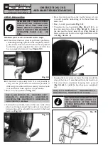
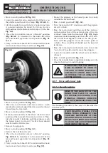
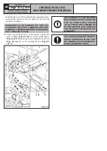
been completely removed (see
Figure 32
).
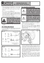
Fig. 32
B.
If the wheel is especially hard, it is not possible to
carry out the procedure described in point
A
. A
different procedure will be necessary: use the hook
tool and follow this sequence of operations:
• Move to work position
C
(
Fig. 12
).
Only for GG40256.11SL - GG40256.11ST -
GG40256.15 - GG40256A.15 - GG40256D.15
- GG40256.15SL - GG60360.15 - GG60360A.15
- GG60360D.15 versions
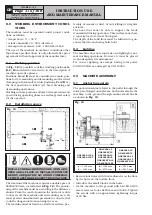
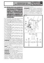
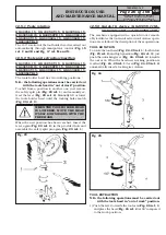
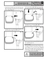
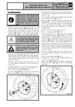
• Position the tool holder arm on the outer side of the
wheel and bring forward the hook tool, inserting it
between rim and bead until it is secured to the bead
itself (see
Fig. 33
).
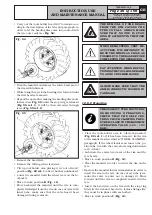
Fig. 33
• Move the rim away from the tool by about 4-5 cm
to avoid possible unhooking of the bead from the
same tool.
• Move to work position
A
(
Fig. 12
).
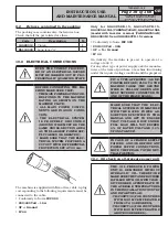
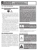
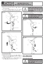
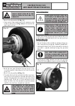
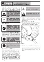
• Translate the tool outwards (
Fig. 34 ref. 2
) to al-
low easy insertion of lever (
Fig. 34 ref. 1
) between
the rim and the bead; insert lever (
Fig. 34 ref. 1
)
between rim and bead on the right-hand side of the
tool (
Fig. 34 ref. 2
).
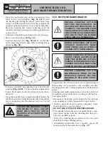
Fig. 34
1
2
• Keeping the lever pressed, lower the wheel until the
edge of the rim is 5 mm distant from the hook tool.
• Turn the wheel clockwise keeping lever pressed
(
Fig. 34 ref. 1
) until the bead has gone completely
out.
Only for GG40256T.15 - GG40256TD.15 -
GG60360T.15 - GG60360TD.15 versions
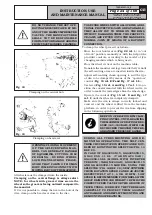
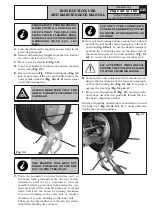
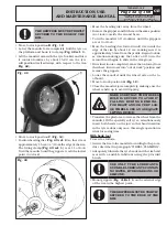
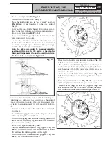
BEFORE STARTING DEMOUNTING
THE 1
ST
BEAD THE SPRING LO-
CKING DEVICE OF THE TOOL
MUST BE EXTRACTED OUTWARDS
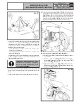
(FIG. 35 REF. 1).
Fig. 35

