INSTRUCTION, USE
AND MAINTENANCE MANUAL
GB
Page 26 of 168
7522-M001-14_P
GG40256.11SL - GG40256.11ST - GG40256.15
GG40256T.15 - GG40256A.15 - GG40256D.15
GG40256TD.15 - GG40256.15SL - GG60360.15
GG60360T.15 - GG60360A.15 - GG60360D.15 - GG60360TD.15
12.5.1 Tools rotation
GG40256.15, GG40256T.15, GG40256A.15,
GG40256D.15, GG40256TD.15, GG60360.15,
GG60360T.15, GG60360A.15, GG60360D.15,
GG60360TD.15
The 180° rotation of the tool holder head is carried out
automatically through manipulator control (
Fig. 15
ref. C and D and Fig. 17 ref. M and N
).
12.5.2 Tools unit extraction/insertion
GG40256.15, GG40256T.15, GG40256A.15,
GG40256D.15, GG40256TD.15, GG60360.15,
GG60360T.15, GG60360A.15, GG60360D.15,
GG60360TD.15
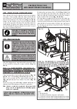
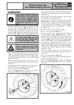
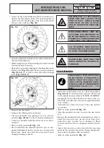
The tools holder head has two working positions.
N.B.: the following operations must be carried out
with the tools head in “out of work” position.
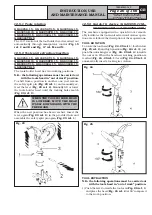
To shift from a position to another one, just remove
the safety split pin (
Fig. 23 ref. 1
) and manually ex-
tract the lever (
Fig. 23 ref. 2
). Manually lift or lower
the tools holder head until the locking holes match
(
Fig. 23 ref. 3
).
WHEN THE TOOL HOLDER HEAD
IS LOWERED, MOVE THE HEAD
ITSELF DOWNWARDS WITH THE
FREE HAND.
When the new position has been reached, insert the
lever again (
Fig. 23 ref. 2
) in the provided hole and
assemble the safety split pin again (
Fig. 23 ref. 1
).
Fig. 23
12.5.3 Quick-fit device (GG40256.11SL,
GG40256.11ST and GG40256.15SL)
The machine, equipped with a quick-fit tool, remark-
ably facilitates the tools unit extraction/rotation opera-
tions. Here follows the description of these operations:
TOOL ROTATION
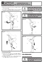
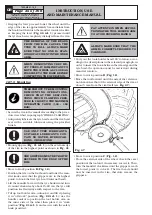
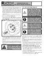
To rotate the tool head (
Fig. 24 - 25 ref. 1
) (both in low
(
Fig. 25 ref. 2
) and high position (
Fig. 24 ref. 3
)) just
push the unlocking lever (
Fig. 24 - 25 ref. 4
) towards
the tool arm. When the head new working position is
reached (
Fig. 24 - 25 ref. 1
) lever (
Fig. 24 - 25 ref. 4
)
automatically inserts locking its rotation.
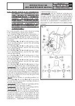
Fig. 24
Fig. 25
TOOL EXTRACTION
N.B.: the following operations must be carried out
with the tools head in “out of work” position.
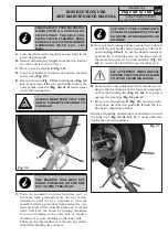
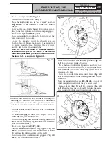
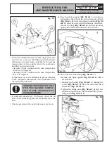
1) Push the lever towards the tool arm (
Fig. 26 ref. 1
)
and place the head (
Fig. 26 ref. 2
) at 90° compared
to the work position.

