4-column
electro-hydraulic lift
Mod. Z31
Use, maintenance and spare parts manual
Page 11
ASSEMBLY INSTRUCTIONS
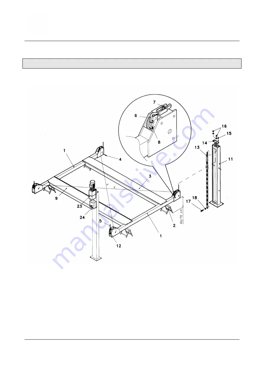
Fig. 3 – Assembly instructions layout
1. Put the two crosspieces (Ref.1-Fig. 3) in place using four 60-cm-high
stands (Ref.2-Fig. 3); the two crosspieces must be parallel to each other
and must have the electric cables and air pipe protections on the outer
side.
2. Release the ropes from the fixed footboard (Ref.9-Fig. 3).
3. Place the fixed footboard on the two crosspieces (the guide edge, in alto,
must remain inside the lift). The oil, air and cable pipe must remain in the
part where the controls must be located. Unscrew the anti-derailment
screws located in the crosspieces (Ref.4-Fig. 3). Introduce the ropes
(Ref.5-Fig. 3) inside the heads of the crosspieces, fitting them into the
races of the pulleys. Tighten again the anti-derailment screws.


