III. ENGINE REPAIR
55
18. Cylinder shields and air
guides
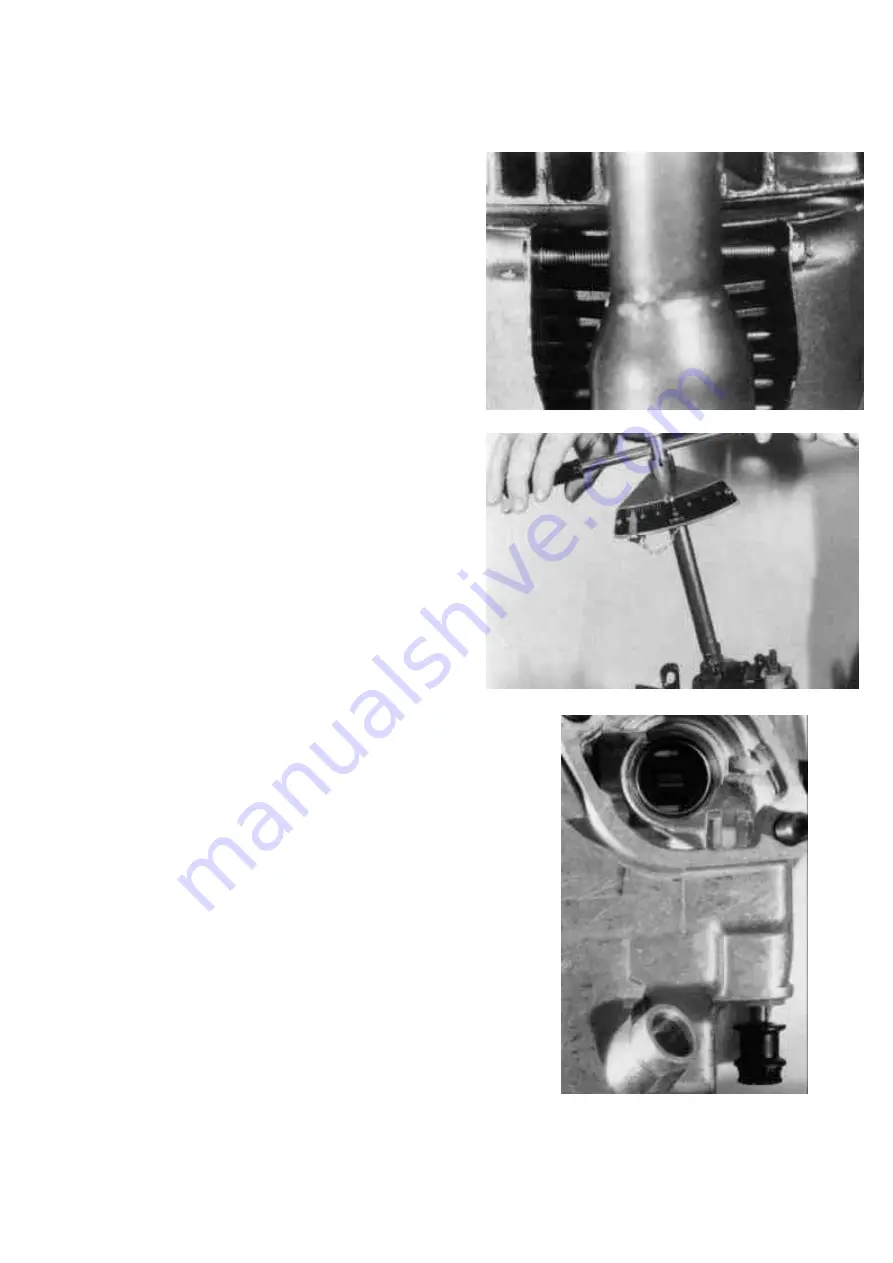
Install both halves of cylinder shields and
the clamping bolt. Do not overtighten the
bolt. It is sufficient when the bold protrudes
about 1-2 mm (0.0394“-0.0787“) out of the
locknut. Install the two air guides on top of
the crankcase.
(Figure 36)
19. Fuel injector
Replace the special washer located in the
cylinder head fuel injector seat.
Attention: Use one gasket only, make
sure that the old one has been taken out.
Install the injector and the clamp. Torque
the two nuts as specified.
(Figure 37)
20. Injection pump
Place acceleration lever in full load position
and pull excess fuel button. The internal
spring pushes the control lever against the
housing. Place rod of the „fuel injection“.
When sliding in the pump the pin of the rod
directly grips into the yoke of the control
lever. Reinstall the injection pump by using
the same number and types of shims as
were on the engine before (see III.5 for
complete injection timing info.)
Attention: First install the paper gasket,
then the shims onto the stud. Shims
should not be in direct contact with the
housing due to insufficient sealing
function.
(Figure 38)
Summary of Contents for 15D Series
Page 8: ...III 1 DISASSEMBLY 10...
Page 9: ...II TECHNICAL DATA 11...
Page 15: ......
Page 27: ...III ENGINE REPAIR 28 III 2 DIMENSION TABLE WEARING PARTS...
Page 28: ...III ENGINE REPAIR 29...
Page 29: ...III ENGINE REPAIR 30...
Page 30: ...III ENGINE REPAIR 31...
Page 31: ...III ENGINE REPAIR 32...
Page 32: ...III ENGINE REPAIR 33...
Page 33: ...III ENGINE REPAIR 34...
Page 34: ...III ENGINE REPAIR 35...
Page 35: ...III ENGINE REPAIR 36...
Page 36: ...III ENGINE REPAIR 37...
Page 37: ...III ENGINE REPAIR 38...
Page 38: ...III ENGINE REPAIR 39...
Page 39: ...III ENGINE REPAIR 40...
Page 40: ...III ENGINE REPAIR 41...
Page 41: ...III ENGINE REPAIR 42 III 3 ENGINE REASSEMBLY...
Page 73: ...74...
Page 74: ...75...
Page 75: ...76...
Page 76: ...77...


