


MP3020
INSTALLATION MANUAL - EN
Edition 1.0 May 2021
Pag. 7 di 12
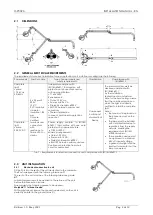
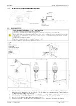
2.4.2
Installation procedure
A
After having fixed as reference point the centre of the chair (A). install
at a distance of 650mm and 150mm, according to the directions given
in the picture.
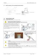
B.
Unfit the flange (7) by removing the nuts (12) and washers (11).
C.
Using the flange (1) as a guide, drill 4 holes in the ceiling Ø14mm.
Fit the 4 expanders (2) in the holes.
Warnings for suspended masses
Safety Component: 2, 3 and 4
D
. Take the flange (1). Pass the power cable through the cable gland (5),
then push the flange (1) to the ceiling;
do not choke the cable between the flange (1) and the ceiling.
Secure the 4 screws (3) and washers (4) in the the 4 holes.
Lock with the special wrench (installation accessory) the screws (3).
E.
Connect the power cable to the terminal block (6)
F.
Fit the 2 guides (23) to the screws (8) and fix them with
the nuts (9) and washers (10)
G.
Calculate the proper height of the column (14), according to the
Formula:
L=H-DHC-1020 mm.
Cut the exceeding column (14) part on the side were no lateral holes
are present
I.
Fit on the column (14) the ring(15) at about 300 mm height
(it is only temporary position to allow the assembling)
J.
Insert the ceiling light support (16) on the column (14)
K.
Fit the column (14) in the special bore of the column fixing flange (7)
M.
Hook the unit assembled [column flange (7) + column (14)] to the fixing guides (23), fitting the 4 holes of the flange (7) to
the screws (8).
Warnings for suspended masses
H.
Insert the column (14) in the flange (7) and make the marks on
the column (14) the position of the holes on the flange (7).
Remove the column and drill two Ø 8 holes at the marked points.
Warnings for suspended masses
L.
Lock the screw (13) and the two screws (18) with hexagonal spanners
(installation accessory).
Tighten sturdily the screw (13) and make sure the
screws (18) have passed through the bores on the column (14)
Summary of Contents for MP3020
Page 1: ......


