


MP3020
INSTALLATION MANUAL - EN
Edition 1.0 May 2021
Pag. 10 di 12
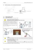
E.
Connect the lamp wires to the terminal Electrical connector (5) (see wiring diagram below) including the
grounding wire.
F.
Connect
the
wires
coming
out
of
the
wall
to
the
terminal
board,
in
the
case had been previously walled up. In the absence of this precaution, the connection
it must be carried out with an external flying cable, to be introduced into the cable gland (10).
G.
Mount the cover (7) using the screws (8).
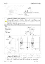
2.5.1
Electrical drawing – wall mounting without transformer
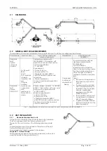
2.6
FLOOR MOUNTING
Warnings for electrical danger
Warning for danger of suspended masses
NB1. The device must be installed by specialized technicians
NB2. The power supply inside the room where the installation is carried out must always be switched off.
NB3. Before proceeding with the assembly operations it is necessary to make sure that the floor is able to support the
application. The authorized materials are concrete and natural stone. The wall plugs to be used are those supplied or
equivalent.
NB4. Maximum applicable load: 70 kg
NB5. Install in rooms with an electrical system that complies with the national regulations in force on medical premises (see
§3.2.1 for general description)
NB6. The Lights must be powered and connected according to requirements of table 1).
The resulting medical system must be declared in accordance with IEC / EN 60601-1 by the installer
.Once the fixing point has been established with
reference (a) the center of the chair, drill four
holes
diameter
D14
in
the
floor
in
correspondence with the holes in the floor
support (13).
A.
Prepare the floor support (13) by passing the
washer (7) and the screw (6);
B.
screw the wall plugs (12) onto the screws (6)
for a few turns, pass the supply wire through
the cable fairlead (11)
-
Insert the four wall plugs (12) into the holes
and lock the screws (6) using the appropriate
hexagonal key, taking care not to damage
the wire between the floor support (13) and
the floor itself.
C.
Apply the four caps plugs (5) to the holes in
the floor support (13).
D.
Unscrew the screws (8) and remove the cover
plate (9)
E.
Connect the power supply wire to the
terminal connector (10), including the ground
cable.
F.
Place the column (4) to the floor support (13),
during the fixing, check the perpendicularity
of the column.
G.
Place the bush (2) to the column (4) with the
three screws (3), taking care to orient the
holes in the bush (2) in correspondence with
the screw housings on the column (4).
Connect the lamp lead to the terminal
connectors (10) including the ground cable
H.
Fix the cover plate (9) to the floor support (13)
with the two screws (8).
1. Pin
2. Bush
3. Screw
4. Column
5. Caps
6. Screws
7. Nut
8. Screw
9. Cover
10. Terminal connector
11. Cable Fairlead
12. Wall plugs
13. Wall suport
14. Grani
15. Caps
Summary of Contents for MP3020
Page 1: ......


