


MP3020
INSTALLATION MANUAL - EN
Edition 1.0 May 2021
Pag. 5 di 12
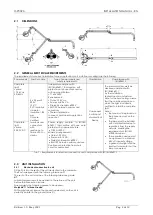
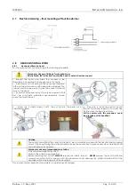
Take care that the fixed arm is parallel to ground in
each position.
Check the light stays balanced in all positions and no drifting
of the swivel arm occurs. If necessary, adjust the force on
the spring by screwing or unscrewing the nut (B) with the
suitable tool until the arm is balanced.
2.3.2
Power Supply connection
Check the output voltage from power supply according to table 1.
Connect the power supply cable according to the specifications outlined in Tab. 1.
Color specification for the cables:
Neutral: blue
Phase: brown
The power supply cable on the complete light is supplied without any connector or terminal to allow connection according
to the specifications of the combination or application.
The functionality and safety of the light does not depend on the polarity of the power supply. Therefore inversion of the
power supply cables will not pose a risk of malfunctioning.
Specification of the Power Supply Cable
2 x 0.5 mm2 (AWG 20, 300 V rating, 105°C, VW-1 flame rate)
PVC insulation
Diameter of insulation 1.85 mm
Only use certified terminals and connectors with resistance to flame VW-1 or similar.
Take care that the device is protected with the fuse as recommended in Tab 1.
2.3.3
Remote Cable connection
Standard remote cable length 4 m
Maximum range from arm on the side of the pin:
2,5 m.
The remote cable must not be lengthened during installation.
Any operation done on the remote cable could affect “EMC” performance.
Connect the cable to two buttons (A and B) with normally open contact
(not supplied) according to the following diagram.
W – White / G - Green / B - Brown
Warnings for electrical interferences causing malfunctioning
if the remote cable terminals are not connected to the unit, always insulate (i.e. with insulation tape) the
terminals.
Function
Button
Operazion
On – Off
A
Press and release
Lux min
B
Press and release
from Lux min, ,back to standard Lux
B
Press and release
Dimmering
A
Press and keep pressed
2.3.4
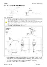
Auto-on setting
To activate or deactivate Auto On Setting proceed as described below:
Switch off the lamp and disconnect the power supply from the unit.
Put the Jumper as showed in the picture on the right.
Connect the power supply and turn on the lamp.
With the lamp turned on, pull out the jumper
To deactivate the Auto-on setting, repeat the procedure.
Summary of Contents for MP3020
Page 1: ......


