background image

41

Revision date: 12.23.15

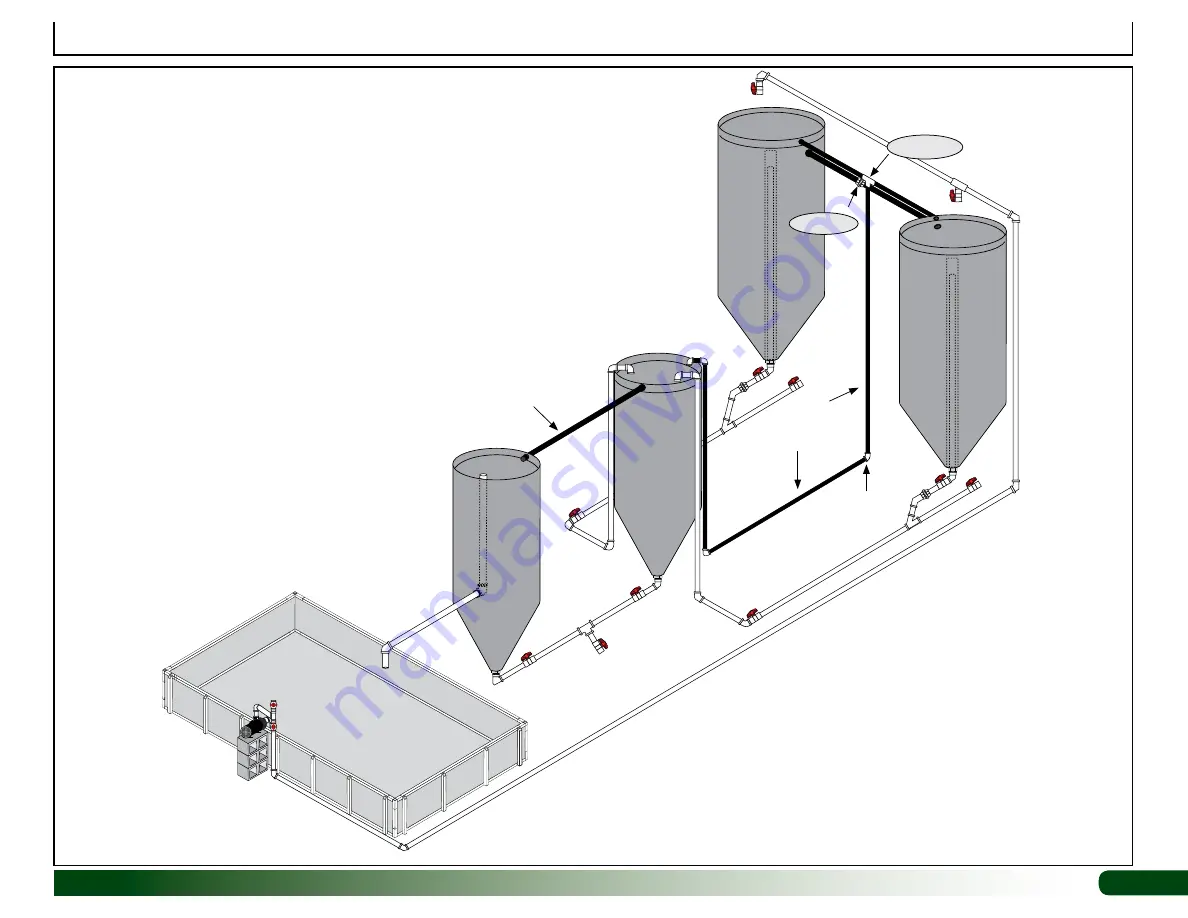
Full Profile: Overflow and Water Level Plumbing

1" PVC 

Overflow 

Tube

1" PVC 

Overflow 

Tube

WF1570

112285

WF1380

WF1570

WF1570 (2)

ATTENTION:

 Distance between tanks has been exaggerated 

to better shown the plumbing. Depending on size and position, 

tanks are typically set 12" to 30" apart. Greater distances may 

require the purchase of additional pvc tubing.

Plumbing identified by the black tubing is the overflow and water 

level plumbing.

The 1" pvc positioned near the top of the tanks is the overflow 

tubing. When water flow is set correctly, water does not typically 

flow through these pipes.

Summary of Contents for 112663

Page 1: ...stem I A balance between hydroponic vegetable production and fish rearing GS Series I Aquaponics Systems allow you to produce high quality produce and fish through the process of combining a hydroponic growing system with a fish producing aquaculture tank Actual system may differ from what is shown 112663 AQUAPONICS SYSTEM I ...

Page 2: ... Fault Circuit Interrupter when working with power tools and cords UNPACK AND IDENTIFY PARTS The following steps will ensure that you have all the necessary parts before you begin assembly 1 Unpack the contents of the shipment and place where you can easily inventory the parts Refer to the Bill of Materials Spec Sheets 2 Verify that all parts listed on the Bill of Materials Spec Sheets are present...

Page 3: ...Keep all fittings in the shipping bags until they are needed WF1380 WF1384 112365 FAPA12 WF1576 2 111045 FA4472B 102921B FALB34B 111906 112817 109260 112285 112710 1 112367 1 1 2 UniSeals WF1570 1 MH1123 1 1 2 WF2995 1 112965 1 1 2 WF8585 2 100442 WF1982 WF3511 WF2198 1 1 2 WF2199 WF1574 1 1 2 111153 2 Check Valve 112366 111148 Pump 109259 Pump WR1095 Tape WF6990 PVC Cement WF6671 WF6684 ...

Page 4: ... water pump and connect pump to the tank plumbing Consult the services of a certified and competent electrician when connecting the pump to power Customer is responsible for supplying a solid stable mounting surface for the water pump 6 Install the air pump connect air stones and place stones in tanks and float bed Install air pump above the water level in the holding tanks to prevent siphoning in...

Page 5: ... additional pvc tubing and or fittings BASIC REQUIREMENTS 1 Assemble float bed on a flat level surface free of debris and objects that could damage the liner Surface must be capable of supporting the weight of the float bed when filled with water 2 Position all tanks on a solid level surface Surface must support the weight of all tanks when filled with water For reference only A gallon of fresh wa...

Page 6: ...utside Sidewall End Wall Evenly Spaced Evenly Spaced 56 1 2 Outside to Outside 16 Sample End Wall 104779 Tube Install vertical tube tight against the 3 way corner insert S15P052 Tube 52 Sidewall 112375 Tube 15 3 4 Vertical Supports 110611 3 Way Insert All Corners S15P016 Tube 16 All Corners End Wall 104779 Tube 96 ...

Page 7: ...5 Cuts 22 FA4472B Tek Screws 100442 Magnetic Nut Setter 1 Install all 16 S15P016 tubes flush with the open end of each 110611 3 way corner connector 3 Install the first and last vertical support for each end or side wall tight against the 3 way corner connectors 2 Install all FA4472B Tek screws into the sides of the fittings Do not install along the top frame rail 4 Install all vertical supports f...

Page 8: ...bly check all connections to verify that Tek screws are properly installed Next measure corner to corner diagonally as shown When dimensions are the same frame is square Finally level the frame Prepare the site inside frame if not on a solid surface such as wood or concrete Actual frame may differ from what is shown ...

Page 9: ...e for the liner Cut panels to the needed dimensions 3 Continue this pattern until the ends and all sides of the frame are insulated 6 Before installing the liner material inspect the bed surface and remove any debris that could damage the liner Insulate the Float Bed Frame Once the frame is level use the rigid board insulation to insulate the sides of the frame and the surface that supports the be...

Page 10: ...the Tek foil Use the supplied duct tape to hold the foil in place during installation Overlap the seams as needed to ensure proper coverage Neatly fold foil at the corners to allow for an easier installation of the bed liner 4 Install Tek Foil Liner Install Tek Foil Inside Frame ...

Page 11: ...it float bed and create holes in rigid board and foil ATTENTION Photos show using special clips to hold tubing These are not supplied Use the supplied duct tape and tape tubing to the foil Once liner is installed and filled with water tubing will not move Do not use metal wire or staples to secure tube NOTE Allow a few feet of tube to extend beyond frame to connect to heating unit Additional purch...

Page 12: ... work the liner into the corner and along the inside of the base rails NOTE These fasteners will be removed after the entire liner is in position and the aluminum retaining strap is prepared for installation 3 Fold the liner evenly into the corner and up and over the top of the frame rails Try to remove as many wrinkles as possible 5 Move to another corner and press that liner into place Required ...

Page 13: ...he float bed to allow the water to seat the liner inside the frame NOTE Once the liner is fully secured there should be no tension on the fasteners Adding water now helps to achieve that result 12 Continue filling until bed is half full 13 Complete the steps to prepare and install the aluminum retaining strap 6 Cut the material as needed to allow it to fit more evenly at the corners ATTENTION Do n...

Page 14: ...using the FA4472B Tek screws Remove Tek screws and washers before installing the aluminum retaining straps 1 Begin at a corner and remove the Tek screw and washer to install first prepared strap 4 Apply slight downward force to stretch liner material and secure strap with Tek screws 2 Align strap with end of frame and attach using the FA4472B Tek screw 5 Continue attaching straps to the frame unti...

Page 15: ... of the material to use as a pattern This tank is larger than the 15 gallon tank used in the biofiltration position using it for the filter pattern will produce a larger filter to better fit inside the smaller tank NOTE If filter is too large trim to the desired size 3 With the tank in place use a scissors to cut around the tank to create the circular secondary filter ATTENTION The remainder of th...

Page 16: ...r the different components set the tank frames and tanks and plumb the system To correctly assemble the plumbing Wrap the threads of all outside the tank fittings a few times using the WR1095 thread tape before assembly Use the WF6990 pvc cement to connect all remaining fittings to the pvc tubing Dry fit all connections before you glue them to ensure everything fits properly IMPORTANT Consult the ...

Page 17: ...kwise 2 Verify that the rubber gasket remains on the threaded male body of the fitting 5 After the nut contacts the tank surface lightly grip it with a large pair of adjustable pliers and tighten Nut should be snug tight Do not overtighten 3 With assistance and the tank on its side slide the fitting into the bottom hole from inside the tank Rubber gasket is inside the tank 6 Inspect the assembly t...

Page 18: ...anks do not need these seals 2 Take the 1 Uniseals for the overflow pipes and install in the upper 2 rim of the tanks as shown 4 Take all remaining 1 1 2 Uniseals and install these in the 2 1 2 pre drilled holes in the upper sides of the tanks NOTE Only some tanks include these pre drilled holes Do not use sharp tools to install Doing so can damage the seal and tank surface NOTE Some tanks may onl...

Page 19: ...w the glue to set See diagram and photo to the right 3 Take the assembly and install it in one of the large fish holding tanks Hand tighten only Do not tape the fitting threads 4 Verify that the top of the pipe reaches to the bottom of the connecting pipe See dashed line in the diagram below 5 Repeat these steps for all remaining standpipes for the fish holding tanks only 6 Set large fish holding ...

Page 20: ...he between the tank pipes Examine the tanks and install according to the positions shown in the diagrams 3 Align the holes of the different tanks After setting tanks in the frames verify they are level Tubing between the larger fish holding tanks is 1 1 2 overflow tubing between the smaller filter and mineralization tanks is 1 Verify fittings and tubing size on the diagrams before you cut and glue...

Page 21: ...re gluing to ensure a proper fit 2 Assemble and install the drain manifolds of the smaller biofiltration and mineralization tanks 3 Assemble and install the drain pipes See photos on the next page Drain Pipe Return Manifold Drain Manifold WF3511 Valve Biofiltration Tank 1 Overflow Pipe IMPORTANT To protect the valve and related fittings do not allow the drain manifold to extend beyond the tank fra...

Page 22: ...nk positions overall layout and location of float bed will affect pipe length Changing layout may require the purchase of additional materials Photo to the right shows the biofiltratoin tank and the mineralization tank as connected by the drain manifolds Length of pvc pipe depends on tank and float bed positions Glue all joints and allow to dry before checking for leaks Individual preferences may ...

Page 23: ...e 1 pvc tubing WF4135 and 1 elbows Glue all joints Slide pipe into the 1 seal in each tank Wet pipe for easier installation Biofiltration Tank 1 Overflow Pipe NOTE Use the FAPA12 u clamp and two Tek screws to secure the 1 overflow tube to the base of the biofiltration tank frame Use the remaining clamp to secure other end to the floor to prevent movement FAPA12 1 pvc 1 Overflow Pipe WF1380 111045 ...

Page 24: ... fish holding tanks to the biofiltration tank Install 1 1 2 Return Pipe to Filter Tank WF3511 WF1574 1 1 2 Return Pipe Biofiltration Tank Return Pipe ATTENTION Plumbing for these assemblies is the same for the other side of the aquaponic system See photo below WF6684 Return pipe from each bank of fish tanks WF1574 WF1574 WF1570 1 1 2 PVC 9f Actual system may differ from what is shown as an example...

Page 25: ... brackets Review diagrams and photos for position See next page for bracket parts and positions ATTENTION Do not center over tank Run lines off center to allow access to tanks for fish harvest and tank maintenance 3 Assemble main supply line and connect to the over the tank pipes 4 Connect main supply line to outlet manifold of water pump as described in Procedure 10 Connect Main Water Pump IMPORT...

Page 26: ... level over tanks Use a socket and drill to drive the 111906 mounting nut into the tank frame Required parts FAK36 Threaded Rod FALB34B 3 8 Nuts 112817 Conduit Hanger 111906 Sammy for 3 8 Rod Install FALB34B nut on each side of hanger A 9g ATTENTION Tank frame design may differ slightly from what is shown Supply Line Supply Line Supply Line NOTE Any extension should remain above the water level in...

Page 27: ...ttach the main supply pipes Follow these basic steps and requirements 1 Read and understand all documentation sent with the water pump before installation 2 Mount the water pump on a solid stable stand near the end of the float bed opposite the tank location Review all photos and diagrams for additional details and an example Customer to supply all materials and fasteners for pump mount and to sec...

Page 28: ...ter connecting the pump as shown lower right open Valve 1 and close Valve 2 Add water to fill the pipe and pump manifold Fig 1 2 Close Valve 1 and open Valve 2 Fig 3 3 Verify that valves above the tanks are open and turn on the pump to begin circulating water throughout the system Fig 3 ATTENTION If the pump starts but does not pump water within a few seconds turn it off immediately and repeat thi...

Page 29: ...stem This hose connects pump to the manifold Position the manifold in a location that will allow uniform tube lengths Air tube length when connected to the manifold and stone should allow the stone to reach to the top of the cone section of the tank Actual manifold setup may differ Secure manifold to mount Slide 111046A tube onto air stone Wet hose or nipple on stone for easier installation Photo ...

Page 30: ... the tubing along the float bed and tank frame Stones should reach to the top of the cone section Connect these stones to PUMP 2 PUMP 1 Use four 4 air stones in each 55 gallon fish holding tank Run the tubing along the tank frame and plumbing Secure using the plastic ties Stones should reach to where the cone section of the tank begins See diagram on previous page Stones can be allowed to float or...

Page 31: ...ine If the water source uses chlorimine to chlorinate the water and not chlorine gas you may need to consider an alternative water source Chlorimine will not off gas and can kill fish 2 Turn on the pumps air and water and check operation Consult the documentation included with the water pump to ensure it is primed properly during startup to allow it to pump water Do not allow it to run dry Check t...

Page 32: ... confirm the biofiltration tank position for your system Biofiltration Tank 55A 15A 15B 55A 2 Cut one 1 twenty foot 20 section from the 109758 roll of netting and set the roll aside 3 Loosely fold one section and push it into the biofiltration tank 4 Loosely fold the last section and push that material into the tank until it is below the top collar of the tank Material may expand above the tank un...

Page 33: ...ump start your biofilter is to obtain some seasoned water from a trusted source such as another aquaponic grower A five gallon bucket or so will help start bacterial growth in your biofilter tank Dump the seasoned water directly into the tank Once the system is inoculated with good bacteria add food These bacteria eat ammonia you can simply add some over the counter ammonia to the water once your ...

Page 34: ...ium that you will use Consult with your sales representative for additional information about growing plants in your aquaponic system 4 4 8 8 Hole Spacing at 8 on center 72 Locations Hole Spacing at 8 on center non staggered 3 6 6 3 Hole Spacing at 6 on center 128 Locations Hole Spacing at 6 on center non staggered A step bit allows for drilling a uniform size hole through the rigid foam board It ...

Page 35: ...the cap There is no assigned hole pattern Drill as many holes as possible without connecting the holes Holes will allow water to pass between tanks but not small fish NOTE If the fish you are growing are smaller than a 1 4 change the drill bit size or create a nursery tank to grow the fish until a specific size allows them to be transferred to a larger tank 4 After preparing the desired number of ...

Page 36: ...se as your fish grow Use the 112742 slotted siphon tube when fish are small As fish grow and more waste is produced replace the 112742 slotted tube or tubes with the 112743 tube with 1 1 8 holes These holes help ensure a consistent water flow as the fish grow Install Siphon Tubes Photo shows the standpipe as installed inside the fish holding tank Air lines to aerator stones are also shown 1 Slide ...

Page 37: ...s always best to monitor tanks and fish to determine if additional net layers are needed to keep the fish in the tanks Secure the netting to the top ring of the tank frame or use other fastening methods to keep the netting in place Frame shown may differ from actual frame Actual frame design may differ Sample system is shown Your system may differ NOTE You can also cover a tank that holds small fi...

Page 38: ...en hose flush the inside of the standpipe by spraying clean water down into the pipe ATTENTION Do not spray between the standpipe and the siphon tube 5 Once water runs clean from the drain pipe repeat the steps for each remaining standpipe in each fish holding tank 6 After cleaning close the valve at the end of the drain pipe A and open valve B for all return lines leading to the biofiltration tan...

Page 39: ...ENTION Distance between tanks has been exaggerated to better shown the plumbing Depending on size and position tanks are typically set 12 to 30 apart Greater distances may require the purchase of additional pvc tubing Plumbing identified by the black tubing is the supply pipe from the pump to the fish holding tanks ...

Page 40: ...74 WF6684 WF1384 Return Manifold Drain Manifold WF1576 WF1576 Drain Manifold WF2198 WF6684 Elbow WF3511 Valve PVC Tube FLOW FLOW ATTENTION Distance between tanks has been exaggerated to better shown the plumbing Depending on size and position tanks are typically set 12 to 30 apart Greater distances may require the purchase of additional pvc tubing Plumbing identified by the black tubing is the ret...

Page 41: ...ed to better shown the plumbing Depending on size and position tanks are typically set 12 to 30 apart Greater distances may require the purchase of additional pvc tubing Plumbing identified by the black tubing is the overflow and water level plumbing The 1 pvc positioned near the top of the tanks is the overflow tubing When water flow is set correctly water does not typically flow through these pi...

Page 42: ...42 Revision date 12 23 15 PAGE RESERVED FOR CUSTOMER NOTES AND RECORDS ...

Page 43: ...43 Revision date 12 23 15 PAGE RESERVED FOR CUSTOMER NOTES AND RECORDS ...

Reviews: