SECTION 10 -- ENGINE -- CHAPTER 1
65
3. Remove the cap and determine the clearance by
comparing the width of the calibrated wire (2)
against the graduated scale printed on the pack-
et (1) containing the wire.
MIF1078A
119
4. Check that the clearance is the one prescribed
on page 8, then lubricate the big end half bear-
ings and permanently mount them, tightening the
connecting rod cap retaining bolts as described
on page 13.
NOTE:
Before permanently fitting the connecting rod
cap retaining bolts, check that their diameter, mea-
sured at the center of the length of the thread, is no
less than 0.1 mm (0.0039 in) of the diameter mea-
sured at approximately 10 mm (0.3937 in) from the
end of the bolt.
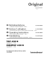
5. Check by hand that the connecting rods (1) run
axially on the crankshaft journals and their end
float measured with a feeler gauge (2) is as pre-
scribed on page 9.
MIF1079A
120
Fitting the Thermostat Valve
(Disassembly operation 55.)
1. Assemble the thermostat valve (2) to its associat-
ed body (1) with the screws (3).
MIF1124A
121
Summary of Contents for 90
Page 132: ...132 SECTION 10 ENGINE CHAPTER 1 ...