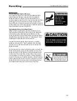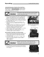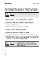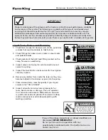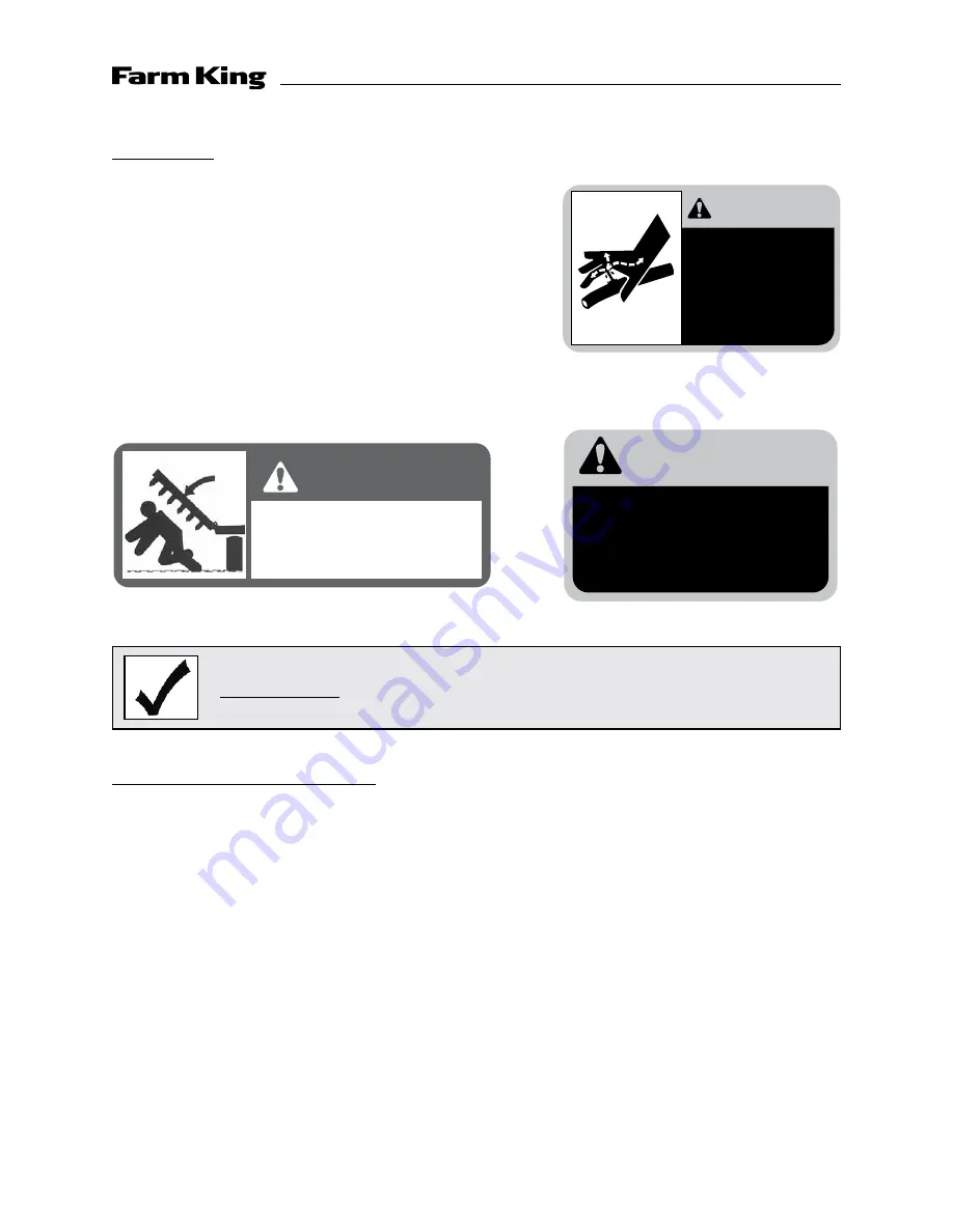
WARNING
004774
KEEP HANDS AND
BODY AWAY FROM
AREAS WHICH
EJECT FLUIDS UNDER
HIGH PRESSURE
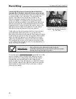
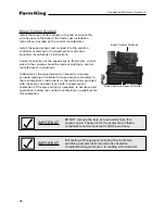
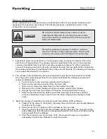
CAUTION
USE CYLINDER LOCKUP WHEN
SERVICING OR STORING UNIT
Hydraulics
1. Inspect cylinder shafts for corrosion or damage. Repair
or replace shaft to avoid hydraulic leaks or cylinder
failure.
2. Inspect hydraulic hoses. Replace any hose that shows
signs of wear or damage.
3. Removing hydraulic hoses for any reason requires that
you plumb them back to their original position. Failure
to do this may result in incorrect operation and may
damage the sprayer. See Section F for the hydraulic
plumbing schematic.
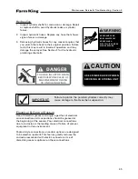
IMPORTANT
Failure to plumb the parallel cylinders correctly may
cause damage to the Henschen suspension.
Electrical & Control System
Use of dielectric grease is strongly urged for all electrical
wire connections. All connections should be greased at
the beginning of the season. Poor electrical connections
due to corrosion is the leading cause of failure of sprayer
equipment in this environment.
Packard style connections on certain options are designed
to be weather resistant. This feature greatly reduces the
corrosion associated with electric connectors. Use of
dielectric grease is optional on these connections.
Maintenance, Service & Troubleshooting - Section E
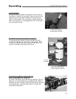
DANGER
TO AVOID INJURY OR DEATH
KEEP EVERYONE CLEAR OF
MACHINE WHEN FOLDING
OR UNFOLDING WINGS
45
Summary of Contents for 1600
Page 1: ...Operator and Parts Manual 1600 High Clearance Sprayer 04 2010 SXL 26030 ...
Page 5: ...Safety Instruction Section A 5 ...
Page 11: ...Safety Decal Placement Safety Instructions Section A 11 ...
Page 12: ...Notes Safety Instructions Section A 12 ...
Page 13: ...Operation Instructions Section B 13 ...
Page 29: ...Connection Startup Section C 29 ...
Page 38: ...Connection Startup Section C Notes 38 ...
Page 39: ...Storage Section D 39 ...
Page 43: ...Maintenance Service Troubleshooting Section E 43 ...
Page 50: ...Maintenance Service Troubleshooting Section E Notes 50 ...
Page 51: ...Parts Schematics Section F 51 ...
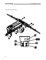
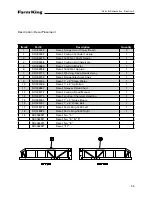
Page 52: ...19 Description Decal Placement Parts Schematics Section F 52 ...
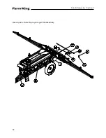
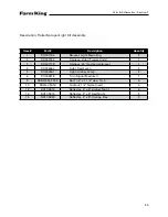
Page 54: ...Description Trailer Sprayer Light Kit Assembly Parts Schematics Section F 54 ...
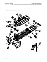
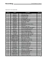
Page 56: ...Description Frame Assembly Parts Schematics Section F 56 ...
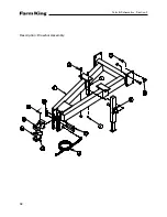
Page 58: ...Description Drawbar Assembly Parts Schematics Section F 58 ...
Page 60: ...Description 10 Bolt Adjustable Axle Assembly Parts Schematics Section F 60 ...
Page 62: ...Description Cradle Assembly Parts Schematics Section F 62 ...
Page 64: ...Description Tank Spreader and Sight Gauge Parts Schematics Section F 64 ...
Page 66: ...Parts Schematics Section F Description Fold Over the Top Boom Center Section Assembly 66 ...
Page 68: ...Description Fold Boom Primary Section Assembly Parts Schematics Section F 68 ...
Page 70: ...Description Fold Boom Secondary Breakaway Assembly Parts Schematics Section F 70 ...
Page 72: ...Parts Schematics Section F Notes 72 ...
Page 74: ...Description Sprayer Hydraulic Routing Parts Schematics Section F 74 ...
Page 76: ...Description Fold Over The Top Boom Hydraulic Valve Breakdown Parts Schematics Section F 76 ...
Page 79: ...Parts Schematics Section F Notes 79 ...
Page 82: ...Description Spray Boom Cylinder Assembly Parts Schematics Section F 82 ...
Page 84: ...Description Boom Rephasing Cylinder Assembly Parts Schematics Section F 84 ...
Page 86: ...Description Pump Plumbing Parts Schematics Section F 86 ...
Page 88: ...Parts Schematics Section F Description Tank Plumbing 88 ...
Page 90: ...Description Raven Control Plumbing Parts Schematics Section F 90 ...
Page 93: ...Parts Schematics Section F Notes 93 ...
Page 94: ...Description Valve Mounting 94 Parts Schematics Section F ...
Page 96: ...Description Fold Over the Top Boom Plumbing Kit Parts Schematics Section F 96 ...
Page 98: ...Description Manual Fence Row Plumbing Parts Schematics Section F 98 ...
Page 100: ...Description Eductor Assembly Parts Schematics Section F 100 ...
Page 103: ...Warranty Section G 103 ...

