background image


USE AND MAINTENANCE MANUAL - SECTION 8 


ELEVAH 61 AERIAL PLATFORM – Rev. 03_2020 

Page 8-4 


Checking for chain wear 

(Check the cause of the malfunction before installing the new chain)


Lifting chain 

Manufacturer: REGINA – Model: AL522 


A1 = 19.1 mm ; Dp = 5.09 mm ; P = 15.875 mm ; S = 2.04 mm ; Hi = 12.83 mm 


Elongation: 

Measurement of chain slightly tightened on straight sections 1/5 to 1/15 of the total length. Maximum 
elongation allowed: 2% along the most worn section. 

 
Wear of plate profiles: 

Where the phenomenon is most noticeable: maximum permitted height reduction of 2.5% on one 
side only, 4% if on two sides, in relation to the initial height. 

 
Wear on the side of the chain: 

Replace the chain if the protruding part of the pin heads is worn down by more than 25% or if the 
outer side is worn down by more than 20% of its thickness. 


Summary of Contents for ELEVAH 61

Page 1: ...USE AND MAINTENANCE INSTRUCTIONS Translation of the original instructions This document is the property of Faraone Industrie Spa Any total or partial reproduction without written authorisation by the author or owner is forbidden ...

Page 2: ...D CONTROL STATION 24 V powered machines 4 4 GROUND CONTROL STATION 220 230 V powered machines 4 5 PLATFORM CONTROL CONSOLE 4 6 ACCESS TO THE CAGE 4 8 PARKING THE MACHINE 4 10 TRANSPORT AND LIFTING PROCEDURES 4 11 SECTION 5 EMERGENCY PROCEDURES 5 1 EMERGENCY OPERATION 5 1 REPORTING THE ACCIDENT 5 2 SECTION 6 DAILY INSPECTION 6 1 SECTION 7 ROUTINE MAINTENANCE 7 1 MAINTENANCE EVERY THREE MONTHS 7 2 M...

Page 3: ... COMPLY WITH THE SAFETY PRECAUTIONS SYMBOLS AND TERMS ATTENTION The danger symbol draws attention to potential dangers that might cause injuries To avoid possible injuries or fatal accidents comply with all safety instructions that follow the symbol Arrows are used in the pictures of the machine to indicate the specific points described in the text of the manual Aerial Platform A machine intended ...

Page 4: ... years as long as it is always used for the purposes it is intended for and that the inspections and maintenance described herein are carried out Faraone Industrie Spa deems it necessary to conduct an extensive analysis of all of the structural components every 10 ten years to confirm their integrity NOTICES For machines sold in Italy According to art 71 paragraph 11 of the Italian Legislative Dec...

Page 5: ...lish a maintenance schedule based on the information provided in this manual which must be strictly complied with The owner user operator company granting in leasing person receiving in leasing the machine must not accept responsibility of its operation before having carefully read the manual and completed the training and the functioning procedures guided by an experienced and skilled operator Fo...

Page 6: ...araone Industrie Spa has approved the operation in writing The machine can be switched on at temperatures between 15 C and 40 C Contact Faraone Industrie for machine operation at temperatures not within the indicated range The machine cannot be switched on in environments stated as ATEX unless specifically indicated in the EC certificate of conformity delivered with the machine in question Machine...

Page 7: ...ted area Risk of falls Before using the machine ensure all rails and gates are fixed in the correct position Keep both feet firmly on the floor of the cage Do not arrange ladders boxes steps planks or similar items on the platform to increase the range of action Do not use the extension unit to climb on or off the platform Pay maximum attention when entering or coming out of the platform Ensure th...

Page 8: ... working platform before attempting to free the machine To stabilise the machine and have personnel climb down from the cage use a crane forklift trucks or other adequate equipment For machine without self propeller Do not move the machine with the stabilisers enabled if present or with the extending structure lifted Before moving the machine completely lower the extending structure Danger of crus...

Page 9: ... For machine with self propeller Do not drive at high speed in reserved or tight areas or when reversing TOWING LIFTING AND CARRYING Do not allow personnel to stand on the cage while towing lifting and carrying Only tow the machine in case of emergency faults a power cut or to load unload it Refer to the Emergency procedures section in this manual Before towing lifting and carrying make sure that ...

Page 10: ...VE PERSONS TO THEIR WORK POSITIONS FROM WHERE THEY ARE TO CARRY OUT THEIR TASKS FROM THE CAGE THE ELEVAH 61 AERIAL PLATFORM MUST BE USED ONLY FOR THE PURPOSES FOR WHICH IT WAS CONCEIVED ANY OTHER USE IS CONSIDERED IMPROPER ATTENTION THE USER MUST OBTAIN APPROVAL AND GUIDELINES FROM THE MANUFACTURER ON SPECIAL OPERATING METHODS OR CONDITIONS NOT COVERED IN THOSE SPECIFIED BY THE MANUFACTURER ...

Page 11: ...nual maximum horizontal side force 200 N 200 N Maximum hydraulic plant pressure 80 bar 80 bar Capacity of the hydraulic tank 2 Litres 2 Litres Power supply Battery powered 220V power supply 2 AGM 12V 40 Ah 220 V 50 60 Hz 2 AGM 12V 40 Ah 220 V 50 60 Hz Operators inside the cage 1 1 Maximum capacity in the cage 200 kg 200 kg Maximum work height from the ground to the floor of the cage With stabilise...

Page 12: ...n oil hydraulic cylinder is installed between the first and second profile powered by the hydraulic unit to lift the structure The chains interconnect the extending structure elements so that they lift simultaneously CAGE The cage is completely made of extruded aluminium profiles The base floor is made of an aluminium sheet coated with a non slip protection EXPOSURE TO VIBRATIONS The machine does ...

Page 13: ... 5 Knowledge of the mechanical operation of the machine sufficient to enable recognising of a fault 6 Safe methods for using the machine in presence of overhead obstacles other moving equipment and obstacles depressions holes and descents 7 Methods to avoid dangers due to unprotected electric conductors 8 Requisites of a particular work or particular application of the machine Training supervision...

Page 14: ...etailed operations a Make sure the control console is correctly assembled and securely fastened b Lift and lower the cage checking that lifting and lowering happen regularly c Activate all functions and check the correct operation of all end run switches main and activation switches Machine brakes Drive the machine on a slope not exceeding the nominal functioning capacity on a slope and stop it to...

Page 15: ... lines protrusions etc RISK OF ELECTROCUTION AND IMPACT WITH EXCESSIVE LOADS COMPARED TO LIMITS ALLOWED DANGER OF LOSS OF STABILITY AND OVERTURNING ON FLOORING WITH STRENGTH LOWER THAN THE WEIGHT OF THE MACHINE DANGER OF LOSS OF STABILITY AND OVERTURNING IN ALL CIRCUMSTANCES NOT SPECIFCALLY INDICATED UNDER OPERATING CONDITIONS IN THIS MANUAL GENERAL DANGER ATTENTION THE ELECTRICAL SYSTEM OF THE MA...

Page 16: ...ertical Do not cause dangerous vibrations and or oscillations that would result in loss of machine stability and possible tipping over ATTENTION THE MACHINE IS WITHOUT AN AUTOMATIC BASE LEVELLING VERIFICATION SYSTEM BEFORE PROCEEDING WITH THE ASCENT DESCENT PHASE VERIFY CORRECT INCLINATION OF THE BASE BY VISUALLY CHECKING THE SPIRIT LEVELS THE SPIRIT LEVELS MUST BE CENTRAL COMPARED TO THE INDICATO...

Page 17: ...RS WHEN USING THE MACHINE WITHOUT STABILISERS AND WITH THE BASE NOT COMPLETELY LEVEL AVOID LIFTING THE CAGE TO PREVENT THE MACHINE FROM TIPPING OVER ATTENTION AFTER POSITIONING THE MACHINE AND MAKING SURE THE BASE IS LEVEL INSERT THE BRAKES ON THE SWIVEL WHEELS IN ORDER TO PREVENT THE MACHINE FROM INVOLUNTARILY MOVING WHEN LIFTING LOWERING THE CAGE AND DURING OPERATIONS AT HEIGHTS LOCKING THE 4 SA...

Page 18: ...s of the machine sensors ballasts etc Prohibition to remove or tamper with the safety and protection devices of the machine Prohibition to climb on or off the cage in places other than the arranged gate Prohibition to increase outreach or work height of the mobile work aerial platform using additional equipment for example ladders Prohibition to induce oscillations on the machine so as not to make...

Page 19: ...ARRIED OUT BY THE EMPLOYER CAUTION ANY FENCING ENCLOSING THE MACHINE S WORK AREA AND ANY ADDITIONAL SAFETY SIGNS TO BE USED FOR THAT AREA MUST BE VERIFIED BASED ON THE SPECIFIC RISK ASSESSMENT CARRIED OUT BY THE EMPLOYER ATTENTION REGARDING ITALIAN LEGISLATION LEGISLATIVE DECREE 81 2008 REQUIRES THE USE OF SUITABLE SAFETY BELTS IN THE CASE OF ALL EXTENDING BRIDGES AND SIMILAR THIS MEASURE APPLIES ...

Page 20: ...chines do not constitute any danger for the operator who is on the cage The level of continuous sound pressure A measurement on the cage is less than 70 db A MACHINE OPERATION Preliminary operations It is necessary for the following control conditions to be satisfied before activating the machine from the cage controls The voltage of the batteries if included must be sufficient to activate the mac...

Page 21: ...ator action and is indicated by a GREEN LED on While using the machine battery charge will change from fully charged indicated by the green LED to partially charged indicated by the orange LED to low battery indicated by the red LED Carry out the following operations carefully Charging must be carried out in a well ventilated area where it is forbidden to smoke and use naked flames It is recommend...

Page 22: ... If the machine is equipped with a plug connecting it to a 220 230 V 50 60 Hz system to power the machine it is sufficient to connect the power plug to an external electrical system ATTENTION CONNECT THE MACHINE TO A POWER SYSTEM THAT IS COMPLIANT WITH THE APPLICABLE LAW AND IN A GOOD MAINTENANCE CONDITION ...

Page 23: ...hines 1 Emergency stop switch off button Emergency stop switch off button NOTE in order for the machine to operate the emergency stop switch off button on the machine must be on RESTORE POWER SUPPLY DISCONNECTION PUSH INWARDS to engage the emergency stop POWER SUPPLY CONNECTION PULL OUTWARDS to restore the emergency stop 1 ...

Page 24: ...tion socket to external 220 V power supply ATTENTION PREVENT UNAUTHORISED USE BY SWITCHING OFF THE MACHINE SWITCHING OFF THE MAIN POWER SWITCH AND REMOVING THE ENABLING KEY Emergency stop switch off button NOTE in order for the machine to operate the emergency stop switch off button on the machine must be on RESTORE POWER SUPPLY DISCONNECTION PUSH INWARDS to engage the emergency stop POWER SUPPLY ...

Page 25: ...lowing conditions of the controls Ground control station The Emergency stop switch off button must be in RESTORE position POWER SUPPLY CONNECTED Platform console The emergency stop switch off button must be in RESTORE position POWER SUPPLY CONNECTED Emergency stop switch off button NOTE in order for the machine to operate the emergency stop switch off button on the machine must be on RESTORE POWER...

Page 26: ... TO THE BASE LEVELLING CONTROL SYSTEM ATTENTION INSTALL THE STABILISING FEET IN ORDER TO REACH THE MACHINE S MAXIMUM WORKING HEIGHT INSERT THE STABILISERS INTO THE APPROPRIATE SEATS UNTIL THEY STOP AND BLOCK THEM BY TIGHTENING THE SUPPLIED SAFETY PIN LEVEL THE BASE BY ADJUSTING THE STABILISER S FEET PAY THE UTMOST ATTENTION WHEN SLIGHTLY LIFTING THE MACHINE S WHEELS SO THAT THEY ONLY REST ON THE S...

Page 27: ... to release the lock by hand To access the cage simply lift the railing Once the operator climbs on to the cage the railing is automatically lowered due to gravity to the closed position ATTENTION MAKE SURE THERE IS NO OBSTACLE THAT COULD BLOCK THE CAGE RAILING FROM CLOSING PROPERLY As soon as the cage starts to rise the hook automatically moves to the locked position thereby preventing the railin...

Page 28: ... the pin always check that the hook is in the locked position Following the manual locking of the parapet the operator will have to manually lower the locking hook until the opening is complete in order to descend from the basket ATTENTION ENSURE HANDS DO NOT REMAIN TRAPPED WHEN CLOSING THE RAIL PLACE THE HANDS ALONG THE AREAS MARKED WITH SPECIFIC ADHESIVE CAUTION DO NOT RAISE LOWER THE CAGE IF TH...

Page 29: ...th your foot by pushing the lever marked by the wording STOP bringing it to its limit switch in the lowest position ATTENTION do not use your hands NOTE To release the brakes push the lever marked FREE with your foot situated on the opposite side of the wheel bringing the limit switch to its lowest position If needed lock the stabilisers in the dedicated support near the front part of the machine ...

Page 30: ...onal Technical Data Table for the machine ATTENTION LOAD THE MACHINE ONTO A HEAVY DUTY VEHICLE HAVING A USEFUL LOAD CAPACITY ABLE TO SUPPORT THE TOTAL WEIGHT OF THE MACHINE CHECK THE GROSS WEIGHT OF THE MACHINE IN THE OPERATIONAL TECHNICAL DATA TABLE OF THE MACHINE ATTENTION FASTEN THE MACHINE SO THAT IT WILL NOT GET DAMAGED DURING TRANSPORT Handling with a forklift truck The machine can be lifted...

Page 31: ... In case of incorrect operation of the controls or power outage the emergency stop must be operated and if necessary a qualified operator must carry out the EMERGENCY DESCENT procedure from the ground Proceed as follows 1 Press the emergency button to disconnect the power supply 2 ATTENTION make sure there are no persons within the working range of the machine 3 Loosen the blocking knob to free th...

Page 32: ... working platform A crane or forklift may be used to stabilise machine movement REPORTING THE ACCIDENT Faraone Industrie Spa must be immediately informed of any incidents involving a Faraone product Contact the factory by telephone and provide all the necessary details even in case no injuries or evident damage to property are involved ATTENTION AFTER AN ACCIDENT INSPECT THE ENTIRE MACHINE AND CHE...

Page 33: ... loose wires or cables hanging underneath the base check for any dents rupture or cracks on the profiles c Manual descent control valve See note pertaining to functional check d Stabilisers if present Check for dents on the aluminium profiles breaks or cracks and check operation of the adjustable stabiliser feet e Motor pump tank unit No conspicuous hydraulic leak hydraulic oil filling level at th...

Page 34: ...ITIES DO NOT TAKE INITIATIVES IF YOU ARE UNSURE OF WHAT YOU ARE DOING ATTENTION TO CARRY OUT MAINTENANCE AND OR CLEANING OPERATIONS ON THE MACHINE THAT REQUIRE THE EXTENDABLE STRUCTURE TO BE IN A PARTIALLY EXTENDED POSITION ANCHOR THE CAGE SAFELY FOR EXAMPLE USING A CONTRASTING STRUT ON THE GROUND TO PREVENT IT FROM ACCIDENTALLY FALLING ONTO THE OPERATOR PERFORMING THE MAINTENANCE OPERATIONS ATTEN...

Page 35: ... of the cage and entrance doors operating correctly Check the controls present in the cage and on the ground if applicable Controls secured legible signs main power supply operable selection switch emergency stop switch in a reset position and legible control signs Check lubrication and wear of the lifting chains When restoring lubrication make sure the chains are not dirty or soiled with mud rubb...

Page 36: ... lowers Verify the absence of debris the integrity of the wheels and the absence of games abnormal movements Contact the Manufacturer for further information and instructions regarding the adjustment of the sliding wheels of the extendable structure when a backlash anomaly is found MAINTENANCE EVERY TWO YEARS Hydraulic Oil Change the hydraulic oil in the tank Refer to the specifications described ...

Page 37: ... maintenance below the cage use a forklift and proceed as follows 1 Disconnect the battery outlet 2 Insert the forks below the cage as indicated in the figure and lift with the utmost care 3 Support the cage with the forklift truck during the entire duration of the maintenance operation 4 When done close the protective cover and slowly lower the cage as far as its end run ...

Page 38: ...egative pole and tighten them 8 Close and lock the protective cover 9 Lower the cage all the way by following the instructions described in paragraph LIFTING THE CAGE FOR MAINTENANCE ATTENTION SHOULD THE BATTERY BE DAMAGED USE THE RELATIVE PERSONAL PROTECTIVE EQUIPMENT TO PROTECT YOUR HANDS AGAINST CHEMICAL AGGRESSION WHEN REPLACING THE BATTERY DISPOSE OF THE BATTERIES IN ACCORDANCE WITH THE LAWS ...

Page 39: ...be used This phenomenon may be caused by corrosion or cold micro welding 5 Turned pins This is the consequence of incorrect lubrication and the aforementioned phenomenon of stiffened joints This phenomenon is easily recognised by the difference in the pin clinching positions compared to factory standard 6 Pins coming out of their housings A direct consequence of the stiff joints of turned pins 7 W...

Page 40: ...nt of chain slightly tightened on straight sections 1 5 to 1 15 of the total length Maximum elongation allowed 2 along the most worn section Wear of plate profiles Where the phenomenon is most noticeable maximum permitted height reduction of 2 5 on one side only 4 if on two sides in relation to the initial height Wear on the side of the chain Replace the chain if the protruding part of the pin hea...

Page 41: ...v 03_2020 Page 8 5 ATTENTION FOR FURTHER INFORMATION REGARDING PURCHASE OF SPARE PARTS AND CONSUMABLES PLEASE CONTACT THE MANUFACTURER THE MANUFACTURER DECLINES ALL LIABILITY DUE TO DAMAGE OR MALFUNCTION CAUSED BY USE OF PARTS NOT AUTHORISED BY THE SAID MANUFACTURER ...

Page 42: ...HING AND TRAPPING OF THE UPPER LIMBS 3 DANGER SIGN DANGER FALLING OBJECTS FROM ABOVE 4 PROHIBITION SIGN FOR UNAUTHORISED PERSONNEL TO USE THE MACHINERY 5 PROHIBITION SIGN TO REMOVE THE SAFETY PROTECTIONS AND DEVICES 6 OBLIGATION SIGN CONSULT THE OPERATING MANUAL 7 OBLIGATION SIGN WEAR NON SLIP SHOES 8 INDICATION MANULE BLOCK FOR OPENING THE BASKET 9 INDICATION Cage opening closing coupling point 1...

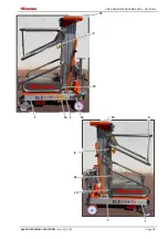
Page 43: ...USE AND MAINTENANCE MANUAL SECTION 9 ELEVAH 61 AERIAL PLATFORM Rev 03_2020 Page 9 2 1 1 16 14 1 1 8 9 9 10 10 15 15 12 ...

Page 44: ...USE AND MAINTENANCE MANUAL SECTION 9 ELEVAH 61 AERIAL PLATFORM Rev 03_2020 Page 9 3 18 1 1 1 1 17 19 9 6 3 4 5 6 7 13 11 2 15 ...

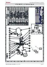
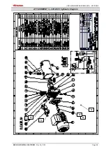
Page 45: ...USE AND MAINTENANCE MANUAL SECTION 9 ELEVAH 61 AERIAL PLATFORM Rev 03_2020 Page 9 4 ATTACHMENT 2 24 V hydraulic diagram 14 10 14 10 10 10 ...

Page 46: ...USE AND MAINTENANCE MANUAL SECTION 9 ELEVAH 61 AERIAL PLATFORM Rev 03_2020 Page 9 5 ATTACHMENT 3 220 230 V hydraulic diagram 14 10 14 10 10 10 ...

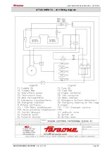
Page 47: ...USE AND MAINTENANCE MANUAL SECTION 9 ELEVAH 61 AERIAL PLATFORM Rev 03_2020 Page 9 6 ATTACHMENT 4 24 V Wiring diagram ...

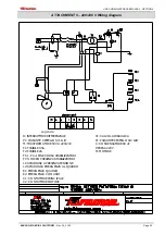
Page 48: ...T1 TRASFORMATORE 50 VA 220 24V F1 FUSIBILE 0 5A FC1 FC4 FINE CORSA STABIILIZZATORI L1 SPIA BIANCA PRESENZA TENSIONE L2 SPIA ROSSA EMERGENZA AL QUADRO FC5 MICRO PRESENZA STABILIZZATORI Legenda C1 CONTATTORE PRINCIPALE C2 CONTATTORE MOTORE F2 FUSIBILE 2A E1 EMERGENZA QUADRO V1 VALVOLA IDRAULICA P1 PULSANTE CESTELLO SU GIU C CONDENSATORE 80 uF P PRESA 220V M MOTORE E2 EMERGENZA COMANDI ...

Page 49: ...Page 9 8 ATTACHMENT 6 Inspection certificate AERIAL PLATFORM ELEVAH 61 Serial number The machine built in compliance with the model that is the object of type testing underwent the following tests Brake test Overload test Operation test Producing a POSITIVE result Tortoreto on ...

Page 50: ...USE AND MAINTENANCE MANUAL SECTION 9 ELEVAH 61 AERIAL PLATFORM Rev 03_2020 Page 9 9 ATTACHMENT 7 Declaration of conformity ...

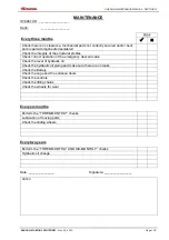
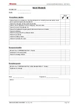
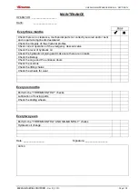
Page 51: ...checks Hydraulic oil change Date _______________ Signature ________________ NOTES DONE Every three months Check there is no clearance mechanical parts not correctly secured and or bent and no parts components desoldered Check the integrity of the structural profiles Check correct operation of the emergency descent valve Check the level of hydraulic oil Check the hydraulic oil piping and make sure ...

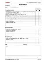
Page 52: ...c oil change Date _______________ Signature ________________ NOTES DONE Every three months Check there is no clearance mechanical parts not correctly secured and or bent and no parts components desoldered Check the integrity of the structural profiles Check correct operation of the emergency descent valve Check the level of hydraulic oil Check the hydraulic oil piping and make sure there are no le...

Page 53: ...c oil change Date _______________ Signature ________________ NOTES DONE Every three months Check there is no clearance mechanical parts not correctly secured and or bent and no parts components desoldered Check the integrity of the structural profiles Check correct operation of the emergency descent valve Check the level of hydraulic oil Check the hydraulic oil piping and make sure there are no le...

Page 54: ...c oil change Date _______________ Signature ________________ NOTES DONE Every three months Check there is no clearance mechanical parts not correctly secured and or bent and no parts components desoldered Check the integrity of the structural profiles Check correct operation of the emergency descent valve Check the level of hydraulic oil Check the hydraulic oil piping and make sure there are no le...

Page 55: ...c oil change Date _______________ Signature ________________ NOTES DONE Every three months Check there is no clearance mechanical parts not correctly secured and or bent and no parts components desoldered Check the integrity of the structural profiles Check correct operation of the emergency descent valve Check the level of hydraulic oil Check the hydraulic oil piping and make sure there are no le...

Page 56: ...c oil change Date _______________ Signature ________________ NOTES DONE Every three months Check there is no clearance mechanical parts not correctly secured and or bent and no parts components desoldered Check the integrity of the structural profiles Check correct operation of the emergency descent valve Check the level of hydraulic oil Check the hydraulic oil piping and make sure there are no le...

Page 57: ...c oil change Date _______________ Signature ________________ NOTES DONE Every three months Check there is no clearance mechanical parts not correctly secured and or bent and no parts components desoldered Check the integrity of the structural profiles Check correct operation of the emergency descent valve Check the level of hydraulic oil Check the hydraulic oil piping and make sure there are no le...

Page 58: ...c oil change Date _______________ Signature ________________ NOTES DONE Every three months Check there is no clearance mechanical parts not correctly secured and or bent and no parts components desoldered Check the integrity of the structural profiles Check correct operation of the emergency descent valve Check the level of hydraulic oil Check the hydraulic oil piping and make sure there are no le...

Page 59: ...c oil change Date _______________ Signature ________________ NOTES DONE Every three months Check there is no clearance mechanical parts not correctly secured and or bent and no parts components desoldered Check the integrity of the structural profiles Check correct operation of the emergency descent valve Check the level of hydraulic oil Check the hydraulic oil piping and make sure there are no le...

Page 60: ...c oil change Date _______________ Signature ________________ NOTES DONE Every three months Check there is no clearance mechanical parts not correctly secured and or bent and no parts components desoldered Check the integrity of the structural profiles Check correct operation of the emergency descent valve Check the level of hydraulic oil Check the hydraulic oil piping and make sure there are no le...

Page 61: ...NOTES ...

Page 62: ...Faraone Industrie Spa Contrada Salino Via San Giovanni 20 64018 Tortoreto TE ITALY Tel 39 0861 77 22 21 fax 39 0861 77 22 22 www faraone com info faraone com ...

Reviews: