PROFESSIONAL AUDIO MONITORING
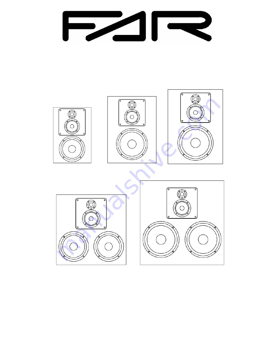
AV10 D
AV 12 D
AV 15 D
AV30 D
AV 40 D
USER MANUAL
Page 1: ...PROFESSIONAL AUDIO MONITORING AV10 D AV 12 D AV 15 D AV30 D AV 40 D USER MANUAL...
Page 2: ...Page 2...
Page 3: ...Output Selection 12 3 3 5 Analogue Full scale selection 13 3 3 6 Curve selection 13 3 3 7 EQ Set selection 15 3 3 8 Speaker relative level 15 3 3 9 Relative speaker delay 15 3 3 10 Shelves and Tilts...
Page 4: ...sional use Part 1 Emission EN 55103 2 Product family standard for audio video audio visual and entertainment apparatus for professional use Part 2 Immunity EN 55022 Information technology equipment Ra...
Page 5: ...r when unused for long periods of time 13 Refer all servicing to qualified service personnel Servicing is required when the apparatus has been damaged in any way such as power supply cord or plug is d...
Page 6: ...ng easy placement in the room and very accurate bass medium reproduction The 3 ways AV monitors are Pro Audio mid field monitors and are excellent for stereo and surround setups in applications such a...
Page 7: ...wards sound purity and clarity This allows a very consistent sound signature across all models The plate being square it is also possible to order the speakers with a medium tweeter assembly rotated b...
Page 8: ...iple functional blocks as described in the next figure SPEAKER EQUALIZATION 10 BAND EQUALIZER CURVE FILTERS SPEAKER DELAY 3 WAY XOVER DRIVER TIME ALIGNMENT DRIVER TIME ALIGNMENT DRIVER TIME ALIGNMENT...
Page 9: ...AR Link Network input RJ45 FAR Link Network output XLR AES EBU digital input XLR AES EBU digital output The power input is an IEC connector 3 1 1 Analogue Input The monitor has a balanced analogue inp...
Page 10: ...ital audio input is selectable via the monitor control menu 2 audio channels are carried over IEC60958 The desired channel is selectable via the monitor control menu The Network digital audio stream a...
Page 11: ...eter definition 3 3 1 Speaker Volume The speaker volume is the first menu item It can range from 40dB to 20 dB by steps of 0 5 dB Figure 6 Volume parameter and values 3 3 2 Digital Channel Selection T...
Page 12: ...by default In this case the monitor will look for a digital stream on the AES EBU input or on the FAR Link network input While scanning the digital inputs the monitor render by default the analogue in...
Page 13: ...inus 6 dB Figure 12 Analogue input full scale selection parameter and possible values When the analogue input level exceeds the selected full scale level the separation symbol of the second display li...
Page 14: ...to emulate the effect of a perforated cinema screen placed in front of the speakers The curve CAR simulates the listening in a car environment A 4 dB boost at 50 Hz and a 2 dB boost at 3 kHz The curv...
Page 15: ...he selected EQ set are permanently displayed on the third field of the bottom line of the LCD Figure 15 EQ Set selection parameter and possible values factory default shown 3 3 8 Speaker relative leve...
Page 16: ...ers can be set from 3 dB to 3 dB by steps of 0 5 dB The corner frequency and Q or S factor can be modified by the SCS Figure 18 Low Shelf gain parameter and possible value 4 3 2 1 0 1 2 3 4 10 100 100...
Page 17: ...gain Frequency 60 Hz and Q 1 5 are factory default Figure 22 Mid Tilt gain parameter and possible value 4 3 2 1 0 1 2 3 4 10 100 1000 10000 100000 Frequency Hz Gain dB Figure 23 Mid tilt frequency res...
Page 18: ...0 1000 10000 100000 Frequency Hz Gain dB Figure 27 High Shelf frequency response for 3dB 2dB 1dB 0dB 1dB 2dB and 3 dB gain values Frequency 4000 Hz and S 1 are factory default 3 3 11 Speaker ID The sp...
Page 19: ...nce muting a speaker set in network master will mute all the speakers in the network When a parameter shall be changed on only one speaker make sure that the speaker is in network slave mode There can...
Page 20: ...ng constraints Due to the signal bridging capabilities of the speakers the digital audio stream does only propagate from the INPUT connector whatever it is to the OUTPUT connector whatever it is As a...
Page 21: ...bling representation 4 1 Analogue Setup 4 1 1 Stereo System This is the easiest setup The two speakers are fed with balanced analogue signals Only the speaker analogue input is used The network cable...
Page 22: ...is then the only link between the 2 speakers The first speaker automatically bridge the AES EBU input to the FAR Link TM network output Output Auto Sel setting ID Input Output Digital Ch LEFT AES EBU...
Page 23: ...of a classical AES EBU output on XLR connector 4 2 2 Stereo 2 1 System A subwoofer can be used to improve the bass extension of a stereo system The subwoofer will use the sum of the left and right cha...
Page 24: ...f 3 XLR cables connected to the DIGITAL IN connector of the LEFT CENTER and SURROUND LEFT speakers As we use the FAR Link TM to carry the digital audio the cabling sequence does matter but is not uniq...
Page 25: ...fer will copy all the settings of the first subwoofer but the spear ID that shall be 9 SUBWOOFER 2 If the proper sequence cannot be respected because the main cabling requirement is to have a speaker...
Page 26: ...problem is to add an additional link using an XLR cable between the LEFT and the RIGHT speakers The appropriate setting of the Input and Output speaker parameters will enable this particular signal r...
Page 27: ...ge 27 or may decide to keep the network cables as short as possible as explained in details in the 5 1 setup description The speaker ID of the surround center can either be set to 6 EXTRA L or 7 EXTRA...
Page 28: ...W 160 W 160 W 300 W 300 W Medium 1 THD 50 W 70 W 70 W 70 W 70 W Tweeter 1 THD 30 W 40 W 40 W 40 W 40 W Common specifications Analogue input Connector XLR Combo balanced input Input impedance 20 kOhms...
Page 29: ...on RJ45 Preset curves FLAT Academy TV Car Club Custom1 to 3 all user configurable 10 band EQ 7 user defined sets Low shelf 3 dB to 3 dB Low tilt 3 dB to 3 dB Mid tilt 3 dB to 3 dB High tilt 3 dB to 3...