FANTEM FT132 Manual Download Page 7

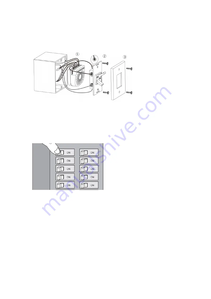
c.  Reinstall the In-Wall Smart Switch (Dual) to the gang box. 
d.  Reinstall the cover onto the gang box. 


Note:   

1)  The gang box should be sized 3

×

2

×

2.75 inch/ 75

×

50

×

70 mm or larger, minimum 

volume 14 in

/ 230cm

3

2)  Use flexible copper conductors only. 

 
5.  Restore Power. 

Restore power at the circuit breaker or fuse. 


Quick start. 

Adding your In-Wall Smart Switch (Dual) to a Z-Wave network. 

 
After your In-Wall Smart Switch (Dual) is installed and powered on, you are now able to manually 
control the In-Wall Smart Switch (Dual) to turn it On/Off directly via pressing your In-Wall Smart 
Switch (Dual)’s Action Button, it is time to add your In-Wall Smart Switch (Dual) to the Z-Wave 
network. To set your Z-Wave gateway/controller into pairing mode, please refer to the respective 
section within your controller instruction manual. 
 
1.  Set your Z-Wave controller into pairing mode. 
2.  Press the Action Button on the In-Wall Smart Switch (Dual) or toggle the external manual 

switch once, the green LED (non-secure indication) will blink to indicate the In-Wall Smart 

Summary of Contents for FT132

Page 1: ...In Wall Smart Switch Dual...

Page 2: ...n connect to 2 external manual switches to control the load ON OFF independently Its surface has a pin socket which can be used for connecting to the touch panel so you can also use the touch panel to...

Page 3: ...on and ensure the wires are not short circuited during the installation which will cause damage to the In Wall Smart Switch Dual Note Your home s main circuit breaker must support the overload protect...

Page 4: ...by the In Wall Smart Switch Dual so please refer to the following diagram to achieve this Note The IN terminal should be connected to the of DC 24V input Wiring diagram of DC24V power input Since the...

Page 5: ...ll above wiring diagrams show that the In Wall Smart Switch Dual uses 2 Way or momentary button switches as the external manual switch for 2 Way connection The below diagram will show you that the In...

Page 6: ...ch Dual d External manual Switch connection Connect 2 18AWG wires to the S1 and S2 on the In Wall Smart Switch Dual e External manual Switch connection Connect 2 18AWG wires form the 2 terminals on th...

Page 7: ...stalled and powered on you are now able to manually control the In Wall Smart Switch Dual to turn it On Off directly via pressing your In Wall Smart Switch Dual s Action Button it is time to add your...

Page 8: ...Wall Smart Switch Dual has been successfully removed from your Z Wave network its RGB LED will remain colourful gradient If the removal was unsuccessful the RGB LED will still be solid following the...

Page 9: ...the In Wall Smart Switch Dual you will be possible to control the In Wall Smart Switch Dual through the Touch panel directly Monitoring Energy Consumption In Wall Smart Switch Dual can report wattage...

Page 10: ...ication will blink to indicate the In Wall Smart Switch Dual is entering into secure pairing mode 3 If the In Wall Smart Switch Dual has been successfully added to your Z Wave network its RGB LED will...

Reviews: