background image


Model 422 & Model 422CC Instruction Manual


D01187869 

Revision A, December 2015 

21  

2.


Install the potentiometer mechanism to be calibrated on the holder. Insert 
the wedge into the open slot nearest the potentiometer ground spring. 

3.


Wind the cord around the potentiometer mechanism frame and over the 
pulley. Place the hanger weight hook in the loop on the end of the cord. 

4.


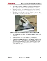
Install the alligator clips to the potentiometer mechanism springs matching 
the wire colors to the contact pin wire colors. 


Figure 5-1 Alligator clips attached to potentiometer mechanism springs 

5.


Insert the calibrator plug into the CALIBRATOR socket on the deck of the 
instrument. 

6.


Within instrument setup, select CALIBRATE - CONSISTENCY. 

7.


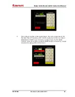
The weight of the hanger on the string is 50g. This is an equivalent of 9 Bc. 
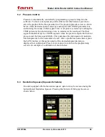
On the touchscreen in the box labeled LOW DATA POINT input 9 on the 
touchpad. Select SAVE LOW VALUE. See below screenshot. It may be 
necessary to tap the calibrator base to loosen any wound tension on the 
spring while in this screen. 

Summary of Contents for 102538934

Page 1: ... 2015 Fann Instrument Company Model 422 Single Cell Model 422CC Dual Cell Auto Consistometer Instruction Manual Manual No D01187869 Revision A Instrument No 102538934 102546632 ...

Page 2: ...hich may be covered by U S Patents Fann Instrument Company reserves the right to make improvements in design construction and appearance of our products without prior notice FANN and the FANN logo are registered trademarks of Fann Instrument Company in the United States and or other countries All other trademarks mentioned in the operating instructions are the exclusive property of the respective ...

Page 3: ...grades 16 5 3 Using the USB Port and Printer 16 5 4 Software Main Menu 17 5 5 Instrument Setup 18 6 Test Setup 27 6 1 Temperature Control 27 6 2 Pressure Control 28 6 3 Hesitation Squeeze Squeeze Schedule 28 6 4 Sample Properties 29 6 5 Alarms 29 6 6 Customer Data 30 6 7 Save Test 30 7 Start Test 31 7 1 Live Testing Screen 31 7 2 Stopping a Test 32 8 View Test 33 8 1 Graph Tab 33 8 2 Scale Tab 34 ...

Page 4: ...me Test 40 11 Maintenance and Basic Servicing 42 11 1 Pressure Vessel and Hydraulic System Maintenance 42 11 2 Potentiometer Mechanism Maintenance 43 11 3 Slurry Cup Maintenance 44 11 4 Replacing the Low Pressure Filter 45 11 5 Potentiometer Mechanism Resistor Replacement 45 11 6 Potentiometer Mechanism Spring Replacement 46 12 Warranty and Returns 47 12 1 Warranty 47 12 2 Returns 47 ...

Page 5: ...mber 2015 5 List of Tables and Figures Table 3 1 Model 422 and Model 422CC Specifications 10 Figure 4 1 Installing the monitor mount 14 Figure 5 1 Alligator clips attached to potentiometer mechanism springs 21 Table 5 1 Consistency as a Function of Weight vs Torque 23 ...

Page 6: ...ular heater surrounding the slurry cup supplies heat to the pressure chamber A centerline thermocouple is provided for determining the temperature of the cement slurry The slurry cup is rotated through the use of an electric motor and a magnetic drive unit The rotational speed of the slurry cup is variable between 25 and 250 rpm to allow the user to study slurries at speeds other than the API pres...

Page 7: ... Revision A December 2015 7 monitor A plot showing temperature pressure and consistency may be plotted on any compatible ink jet printer The data and plots may also be transferred electronically to a network or USB drive for use on a separate computer ...

Page 8: ...er to avoid undesirable consequences MANDATORY ACTION Gives directions that if not observed could result in loss of data or in damage to equipment WARNING Describes an unsafe condition or practice that if not corrected could result in personal injury or threat to health ELECTRICITY WARNING Alerts the operator that there is risk of electric shock HOT SURFACE Alerts the operator that there is a hot ...

Page 9: ...es shut off the compressed air supply to the machine and carefully relieve air pressure from the machine 2 2 Safe Heating Before opening the pressure chamber use the cooling system to lower the temperature to at least 120 F 49 C The machine uses domestic water as coolant Shut off the domestic water supply before servicing NEVER operate the heater on an empty chamber The heater element will quickly...

Page 10: ...eight dual 61 in 155 cm Width single 24 in 61 cm Width dual 48 in 122 cm Depth single 24 in 61 cm Depth dual 30 in 76 cm Weight single 850 lbs 386 kg Weight dual 1600 lb 726 kg Environmental Operating Temperature 32º to 105º F 0 40º C Operating Humidity 0 95 noncondensing Heater Heater Power 5000W per pressure vessel Heater Type Internal cast rod member Heater Control Solid state relay Drive Unit ...

Page 11: ...ight rear of the instrument A number of inch male NPT to 8mm tube fittings are included for international locations The air and water inlet connections may be made with either metal or plastic tubing It is recommended that the water drain lines be made from metal since this line may carry very hot water and steam from time to time Electrical connections are made using the twist lock receptacle on ...

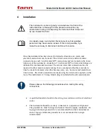
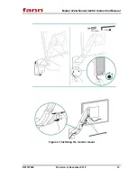
Page 12: ... panel as shown in Figure 4 1 Connect the power cord from the monitor to the A C outlet on the back of the instrument Failure to do so can cause the instrument to malfunction Alternately the touchscreen may be powered using a DC power adapter Plugging the touchscreen and printer into a different outlet creates an undesirable ground loop to occur This creates an unstable electrical system The contr...

Page 13: ...malfunction A USB flash drive may also be connected to the control box in lieu of a printer Test data may be uploaded to the USB drive and then transferred to a computer for archival storage It is considered a best practice to keep a keyboard connected to the computer as it will be necessary to input programming features save data files etc Before attempting to operate the instrument it is recomme...

Page 14: ...Model 422 Model 422CC Instruction Manual D01187869 Revision A December 2015 14 Figure 4 1 Installing the monitor mount ...

Page 15: ...ch surface does NOT use pressure to detect input A light touch is all that is needed Sharp instruments such as pencils pens screwdrivers etc should not be used as they may damage the touch surface The purpose of the touch screen is to provide the user with a single interface to the instrument All instrument operations are accessed and controlled through the touch screen This consistometer is a lea...

Page 16: ... the instrument is connected to one To copy the file from a memory stick put the new file on the memory stick rename the old CementLab exe file to Old exe and copy the new file into the proper folder using Windows Explorer which is accessible from the start menu or My Computer icon The memory stick will generally be the D drive Should the new CementLab exe program not work properly simply delete i...

Page 17: ... selecting it to turn it on Select again to turn off The cooling button is connected to a solenoid valve which is connected to the cooling input located on the back of the instrument Typically water is used at house pressure and temperature However circulating chiller can also be connected If cooling is turned on when start test is activated the cooling will remain on and heating will not ensue Tu...

Page 18: ...pen the pressure release valve thereby releasing any high pressure and start the flow of oil back to the reservoir The pump button located on the main screen is operated by pressing and holding it to turn on and releasing to turn off This button operates the high pressure pump connected to the cylinder The release pressure button is operated by pressing and holding to open and releasing to close T...

Page 19: ...e voltage signal read directly from the I O hardware and it should change as the calibration signal changes When the low data point has been entered press the SAVE LOW VALUE button The user can now enter the high data point on the calibrator and then again on the touchscreen as before The raw value should be different for the low and high data points or there will be a computation error After the ...

Page 20: ...omputation error After the high data point has been established press the SAVE HIGH VALUE button We recommend using a low value of house air pressure and a high value of 20 000psi or near maximum operating pressure The user can now vary the calibration signal and see how the calibrated signal compares with that of the calibration device in the VERIFY NEW CALIBRATION box If the signals compare favo...

Page 21: ...tentiometer mechanism springs matching the wire colors to the contact pin wire colors Figure 5 1 Alligator clips attached to potentiometer mechanism springs 5 Insert the calibrator plug into the CALIBRATOR socket on the deck of the instrument 6 Within instrument setup select CALIBRATE CONSISTENCY 7 The weight of the hanger on the string is 50g This is an equivalent of 9 Bc On the touchscreen in th...

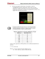
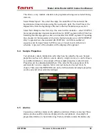
Page 22: ...ghts on the weight hanger This is the equivalent of 100 Bearden Units of Consistency Bc On the touchscreen in the box labeled HIGH DATA POINT input 100 on the touchpad Select SAVE HIGH VALUE It may be necessary to tap the calibrator base to loosen any wound tension in the spring while in this screen ...

Page 23: ...weight to Bc conversions for pot mech By applying additional weights between 0 and 400g and plotting consistency display as a function of applied weight the linearity of the potentiometer mechanism may be assessed Table 5 1 Consistency as a Function of Weight vs Torque WEIGHT g CONSISTENCY Bc 0 4 50 9 100 22 150 35 200 48 250 61 300 74 350 87 400 100 Based on the equation from API Specification 10...

Page 24: ... test will not heat even if it is programmed to heat In other words cooling must be deactivated if a test is to be started even if it is still in automatic mode 5 5 6 Sample Rate This button allows the user to select a sampling rate for taking data Rate is given in number of seconds between samples To save data space and achieve acceptable test resolution a sample rate of 30 or 60 seconds is recom...

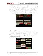
Page 25: ... them manually The default location for Fann test files is C Fann Tests This folder also stores the actual test parameters so any test deleted cannot be run again without reprogramming TEST SETUP 5 5 9 Auto Export This button allows users to store test files in a completely different folder automatically If YES is selected the user is prompted to select a destination folder to store test files If ...

Page 26: ... 422CC Instruction Manual D01187869 Revision A December 2015 26 The Edit Instrument button should only be used when instructed to by Fann and is password protected This application performs changes the config ini file ...

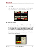
Page 27: ...with the red temperature line The program temperature screen is shown below Enter desired set point values by touching the SET POINT parameter box and entering the values on the keypad Time to set point is selected by touching the TIME parameter box and entering a time in minutes on the touch pad The final segment should always be a SOAK segment where the temperature equals the final test temperat...

Page 28: ...x and entering a time in minutes on the touch pad The final segment should always be a SOAK segment where the pressure equals the final test pressure and the time equals SOAK This guarantees the instrument will maintain final temperature for the remainder of a test After a profile has been entered press the SAVE button At this point a graph of the desired temperature ramp is displayed for confirma...

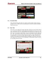
Page 29: ...d Bc STOP Bc An infinite number of sequences can be input Select SAVE to save or Cancel to exit without new schedule A preview of the schedule will be displayed for approval 6 4 Sample Properties Test printouts contain information cells which can be edited by the user Sample properties such as well district cement density weight water etc can be chosen as suitable information An example of these s...

Page 30: ...TEST A pop up appears and requires the user to select a test name This will be the test file name and will be stored in the tests folder located on the C drive An example is shown below Choose a descriptive test name and select save Once this action has been performed the software is ready and programmed for that specific test The next action would be to start test Refer to the start test section ...

Page 31: ...est information and streaming numerical data The user can also create custom header and footer segments of the printed plot Pressing the EXIT button returns the user to the RUN TIME MENU shown below The instrument is equipped with an automatic consistency shutdown and alarm Use the up down arrows to select the consistency value at which the alarm should occur If the Auto Shutdown feature is ON the...

Page 32: ...t in a file on the instrument s local hard disk The default location is C Fann Tests If auto shutdown is enabled the test will be stopped when the Consistency Alarm value has been reached This action has the same effect as the user pressing the STOP TEST button however it also turns the motor and heater off and the cooling water on Note that there is a 5 10 second delay from the time a consistency...

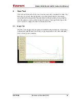
Page 33: ...customized scaled printed and exported The print button will open a dialog box giving the user the option to select a printer or jpeg file option The export button gives the user to option to output a txt file to a destination folder 8 1 Graph Tab The left y axis displays Gel if option is installed on the instrument Consistency Temperature and Pressure Each Curve is given a specific scale color an...

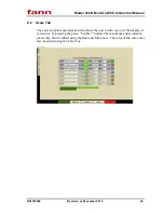
Page 34: ... Scale Tab The scale and plot customization tab allows the user to turn on or off the display of each curve by pressing the green Visible button The maximum and minimum scalar may also be edited using the Max and Min boxes The color of the curve may also be edited using the Color box ...

Page 35: ... units optional and Pressure units optional Depending on the sample time selected the time stamp will be congruent 8 4 Printing Tab The printing tab allows the user to change specific test data that is outputted to the test print out A company logo may be inserted into the print out header by selecting the logo box Pixel size must be 192x96 before the picture can successfully be inserted Values fo...

Page 36: ...he adjustment is finished push the knob in to lock it in place if desired The air pressure is factory set at a default value of around 120psig The pressure release air pressure regulator is located on the underside of the instrument deck and is used to control the air pressure to the pressure release air operated valve AOV Smaller cylinder release pressures require higher air pressure To adjust th...

Page 37: ...he off position The red LED will then power off The electrical box is located at the rear of the instrument along the top There is a panel cover for this box which may be removed to access most of the electrical components Move the touch screen stand forward to allow removal of the top panel cover Always use caution when accessing the electrical box It may be necessary to properly shutdown the ins...

Page 38: ...the pressure vessel Another use for the manual pressure release switch is to evacuate any residual pressure left over from a test When the instrument has finished the drain cylinder procedure there is sometimes residual air pressure from the air inlet pushing the oil back into the reservoir Usually this residual pressure is vented when carefully and slowly loosening the thermocouple nut on top of ...

Page 39: ...entLab has loaded press Test Setup and program a temperature and pressure ramp as described in the Test Setup section 4 Mix the slurry and fill the slurry cup 5 Prior to placing the slurry cup and potentiometer mechanism pot mech into the pressure vessel place the pot mech onto the assembled slurry cup and fit the drive disc and bar using the supplied hex key and drive bar set screw 6 Place the sl...

Page 40: ... waiting for that value to be reached It takes 60 seconds after the value has been reached for the control software to perform shutdown To manually stop a test press Stop Test 2 If manually shut down and the temperature is above ambient press Cool in the main screen If automatic shutdown has been activated cooling will activate automatically 3 Turn the pump off by pressing the Pump On Off button 4...

Page 41: ...out from bottom to top Take care to not bend the paddle shaft 10 Clean all surfaces and threads using a mild detergent Be very careful not to damage the threads or sealing surfaces of components as this may make reassembly difficult 11 Flat diaphragms are generally thrown away after every test depending on the maximum temperature reached during a test 12 Check the potentiometer for proper operatio...

Page 42: ...and seal shaft may be required 2 The cylinder plug threads have been coated with a friction reducing PTFE coating by the factory to help prevent thread seizing and galling However it is still recommended to apply a molybdenum disulfide anti seize compound to the threads periodically If the transfer of the oil from the pressure vessel to the reservoir is slow the filter should be cleaned or replace...

Page 43: ...se 2 Check for broken wires in the potentiometer resistor The resistance should measure between 80 and 100 Ohms The surface of the resistor that is in contact with the wiper may be burnished with a smooth round rod such as a screwdriver blade to reduce noise in the consistency signal if necessary 3 Periodically check that the wiper is making contact with the potentiometer resistor throughout its e...

Page 44: ... cement Lubricate the threads with grease prior to the start of every test 2 It is recommended that hardened cement slugs be pressed out rather than pounded out with a hammer Pressing tends to cause less damage When pressing the slug out be careful not to damage the paddle shaft point or the paddle itself If the slug is not pressed out straight it may cause the cup sleeve to become oval and preven...

Page 45: ...1 4 Replacing the Low Pressure Filter To minimize the mess place a bucket or cup under the filter housing to catch any oil that might spill 1 Make certain the fill button is not active and that the unit is not trying to pump oil Instrument must be in stand by with nothing active 2 Locate the automotive style low pressure oil filter housing near the front door of the instrument 3 Unscrew the filter...

Page 46: ...aring retainer and check the potentiometer mechanism with a calibrating device 11 6 Potentiometer Mechanism Spring Replacement 1 Remove shaft bearing retainer and potentiometer slider 2 Remove old spring The spring should wind tighter when the slider is moved in the counter clockwise direction 3 Install new spring 4 Replace potentiometer slider 5 Loosen the three spring adjuster clamp screws on un...

Page 47: ...on in its catalogs literature or brochures of materials used in the manufacture of its products Fann reserves the right to substitute other materials without notice Fann does not warrant in any way equipment products and material not manufactured by Fann and such will be sold only with the warranties if any that are given by the manufacturer thereof Fann will only pass through to Customer the warr...

Reviews: