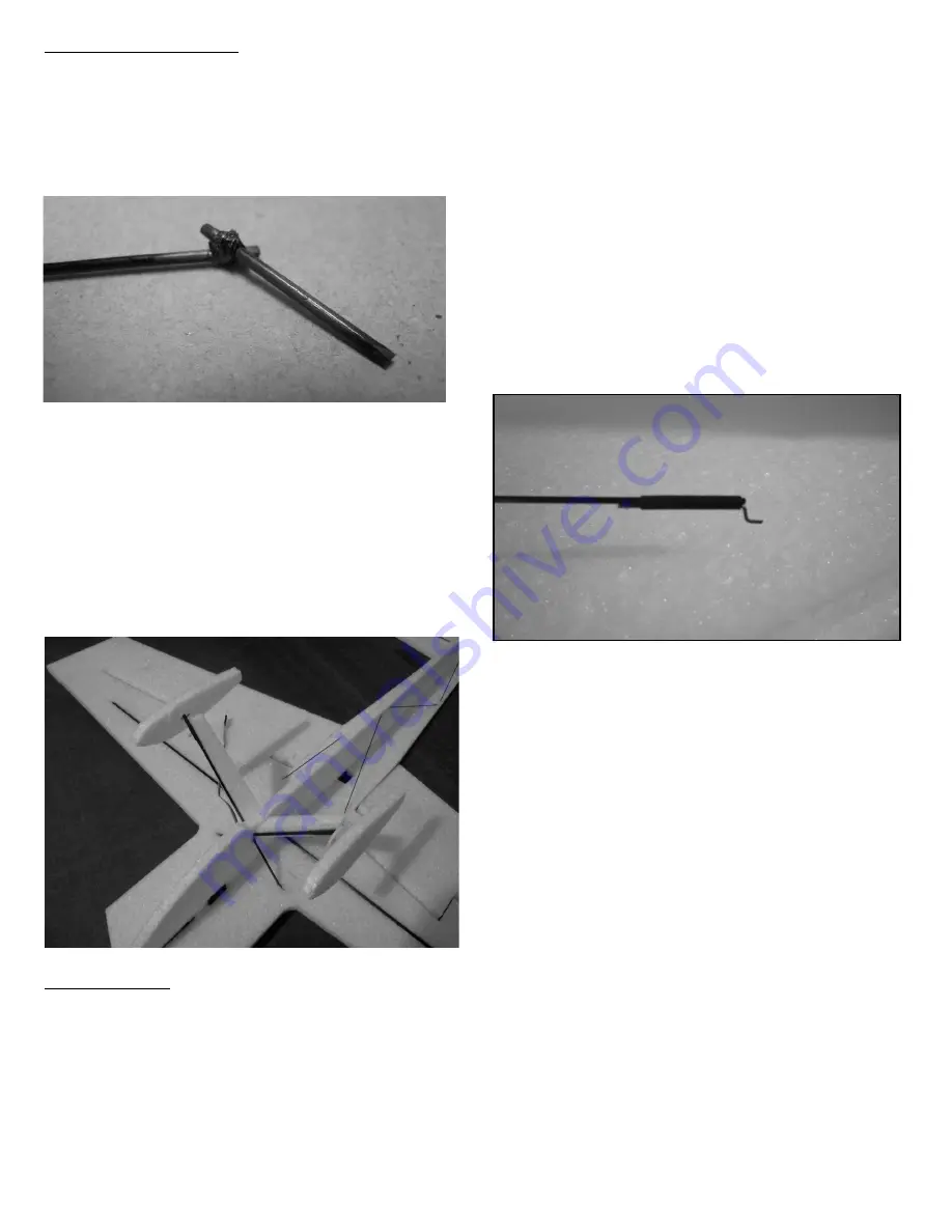
Landing Gear (optional):
Cut 2 pieces of the 1.5mm carbon, 8” long and two
pieces 1” long. Glue them together as shown with a
1/8” overlap at a 45 degree angle. Cut a 6” piece of
string and wrap the joint with it in two directions. CA
the string to secure the axel.
Install the gear legs through the vertical fuselage and
into the bottom of the wing, just behind the leading
edge, but not through the wing. When you have the
axles parallel and even glue the gear legs in place.
Glue the gear pant to the gear leg and the fuselage side.
Slide the wheels onto the axels. Slide the wheel pant
onto the axle and secure in place with a drop of CA
leaving enough room for the wheel to spin freely.
Final assembly:
Install the aileron servo and glue the top vertical
fuselage to the main assembly. Then cut pockets and
install the tail servos. The rudder servo goes on the
left.
Hinge the rudder to the aft of the vertical fuselage
pieces.
Install the motor onto the motor mount and velcro the
speed control and receiver to the lower left side of the
fuselage.
Use an exacto knife to slot the control horn locations in
the ailerons, elevator and rudder. Glue the horns in
place.
With all the surfaces set to zero, measure the distance
between servo arm holes and control horn holes. Cut a
piece of 1.5mm carbon rod for each push rod to the
measured lengths. Cut a 1.5” long piece of 1/32” wire
and make a z-bend on one end. Slide a 1” length of
heat shrink over each end of the carbon rod and then
slide in a z-bend wire. Shrink the heat shrink tubing
with a heat gun or flame. The z-bend wire is not glued
in position yet and can be moved for final adjustments.
Remove the servo arm and assemble the pushrods to
the servo arm and control horns. With the servo
centered reattach the servo horn. Make any final
adjustments to the z-bend location. Use regular (not
foam safe) thin CA to secure the z-bends to the push
rods by placing a drop at each end of the heat shrink
tubing. If you get some CA on the servo or control horn
this is ok and moving the controls will allow the z-
bend to break loose.
Note: This push rod setup will act to save your servos.
In the event of an impact the glue holding the z-bend to
the push rod will likely give before the servo gears. If
the z-bends start to slide in the heat shrink a drop of
CA will secure them again.
3


