13
ENGLISH
SAFETY INSTRUCTIONS
AND WARNINGS
Installation operations are to be carried
out by skilled and qualified installers in ac-
cordance with the instructions in this book-
let and in compliance with the regulations
in force.
DO NOT use the hood if the power supply cable
or other components are damaged:
disconnect
the hood from the electrical power supply and con-
tact the Dealer or an authorised Servicing Dealer for
repairs.
Do not modify the electrical, mechanical or func-
tional structure of the equipment.
Do not personally try to carry out repairs or re-
placements. Interventions carried out by incom-
petent and unauthorised persons can cause seri-
ous damage to the unit or physical and personal
harm, not covered by the Manufacturer's warran-
ty.
WARNINGS FOR THE INSTALLER
TECHNICAL SAFETY
Before installing the hood, check the in-
tegrity and function of each part. Should
anomalies be noted, do not proceed with
installation and contact the Dealer.
Do NOT install the hood if an aesthetic (or cos-
metic) defect has been detected. Put it back into
its original package and contact the dealer.
No claim can be made for aesthetic (or cosmetic)
defects once it has been installed.
During installation, always use personal protective
equipment (e.g.: Safety shoes) and adopt prudent
and proper conduct.
The installation kit (screws and plugs) supplied with
the hood is only to be used on masonry walls: in case
of installation on walls of a different material, assess
other installation options keeping in mind the type
of wall surface and the weight of the hood (indicated
on page 2).
Keep in mind that installations with different types of
fastening systems from those supplied, or which are
not compliant, can cause electrical and mechanical
seal danger.
Do not install the hood outdoors and do not expose
it to atmospheric elements (rain, wind, etc.).
ELECTRICAL SAFETY
The electrical system to which the hood is
to be connected must be in accordance
with local standards and supplied with
earthed connection in compliance with safety
regulations in the country of use. It must also
comply with European standards regarding radio
antistatic properties.
Before installing the hood, check that the electrical
mains power supply corresponds with what is report-
ed on the identification plate located inside the hood.
The socket used to connect the installed equipment
to the electrical power supply must be within reach:
otherwise, install a mains switch to disconnect the
hood when required.
Any changes to the electrical system must be carried
out by a qualified electrician.
The maximum length of the flue fastening screws
(supplied by the manufacturer) must be 1/2" (13 mm).
Use of non-compliant screws with these instructions
can lead to danger of an electrical nature.
Do not try to solve the problem yourself in the event
of equipment malfunction, but contact the Dealer or
an authorised Servicing Department for repairs.
When installing the hood, disconnect
the equipment by removing the plug or
switching off the main switch.
FUMES DISCHARGE SAFETY
Do no connect the equipment to discharge
pipes of fumes produced from combustion
(for example boilers, fireplaces, etc.).
Before installing the hood, ensure that all standards in
force regarding discharge of air out of the room have
been complied with.
USER WARNINGS
These warnings have been drawn up for
your personal safety and those of others.
You are therefore kindly asked to read the
booklet carefully in its entirety before using the
or cleaning the equipment.
The Manufacturer declines all responsibility for
any damage caused directly, or indirectly, to per-
sons, things and pets as a consequence of failing
to comply with the safety warnings indicated in
this booklet.
It is imperative that this instructions booklet is
kept together with the equipment for any future
consultation.
Summary of Contents for Polar FDPLR15I5SS
Page 4: ...4 max 28 2 8 max 720 mm 2 1 8 m m 8 1 2 min 19 11 16 min 500 mm 150 mm 5 15 16 POLAR WALL ...
Page 8: ...8 150 mm 5 15 16 POLAR ISLAND x2 2 1 3 A B C ...
Page 10: ...10 Ø8 mm 5 16 V1 C 1 2 3 M 4 C B G D x V2 1 2 3 4 ...
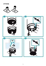
Page 12: ...12 V3 V3 A 1 2 3 S C C 1 2 1 E V3 A B S 2 3 4 OPTIONAL ...
Page 29: ...29 NOTE NOTES ...
Page 30: ...30 NOTE NOTES ...
Page 31: ...31 NOTE NOTES ...


