


INSTALLATION
Check the appliance is electrically safe and gas sound when you have finished.
20
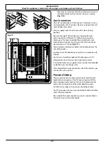
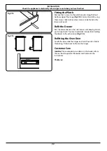
floor level to underside of the top member) and ensure
the bracket does not foul the oven burner assembly
(Fig.7-10)
.
Gas Connection
Must be in accordance with the relevant standards. A hose is
not supplied by with the cooker. Hoses may be purchased at
most builders’ merchants.
The gas supply needs to terminate with a down facing
bayonet.
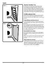
Because the height of the cooker can be adjusted and
each connection is different it is difficult to give precise
dimensions. The hose should be fitted so that both inlet
and outlet connections are vertical so that the hose hangs
downwards in a ‘U’ shape
(Fig.7-11)
.
The connector is located just below the hotplate level at the
rear of the cooker.
For Natural Gas the flexible hose must be in accordance with
B.S.669.
For LP Gas it should be capable of 50mbar pressure, 70°C
temperature rise and carry a red stripe, band or label.
If in doubt contact your supplier. Screw connect the threaded
end of the hose into the gas inlet.
After completing the gas connection, check the cooker is gas
sound with a pressure test.
Pressure Testing
The gas pressure can be measured at one of the left-hand
hotplate burner injectors. Lift off a burner head and fit the
pressure gauge to the injector. Turn on the hotplate burner
and turn on and light one of the other hotplate burners.
For Natural Gas cookers the pressure should be 20mbar.
For LP Gas cookers the pressure should be 29mbar for Butane
and 37mbar for Propane.
Reassemble the burner top making sure it is reassembled in
the correct way on the burner body.
ArtNo.062-0002 - 90SC - Prof+ - Gas connection
��
���
���
��
���
Fig.7-11
ArtNo.070-0005 - Stability bracket
Fig.7-10


