background image

User’s Manual 


ii

Important Safeguards 

1.  Read Instructions 

All the safety and operating instructions should be read before the 

appliance is operated. 

2.  Retain Instructions 

The safety and operating instructions should be retained for future 

reference. 

3.  Cleaning 

Unplug this equipment from the wall outlet before cleaning it.  Do not 

use liquid aerosol cleaners.  Use a damp soft cloth for cleaning. 

4.  Attachments 

Never add any attachments and/or equipment without the approval of 

the manufacturer as such additions may result in the risk of fire, electric 

shock or other personal injury. 

5.  Water and/or Moisture 

Do not use this equipment near water or in contact with water. 

6.  Ventilation 

Place this equipment only in an upright position.  This equipment has an 

open-frame Switching Mode Power Supply (SMPS), which can cause a 

fire or electric shock if anything is inserted through the ventilation holes 

on the side of the equipment. 

7.  Accessories 

Do not place this equipment on an unstable cart, stand or table.  The 

equipment may fall, causing serious injury to a child or adult, and 

serious damage to the equipment.  Wall or shelf mounting should follow 

the manufacturer's instructions, and should use a mounting kit approved 

by the manufacturer. 


This equipment and cart combination should be moved with care.  Quick 

stops, excessive force, and uneven surfaces may cause the equipment 

and cart combination to overturn. 

8.  Power Sources 

This equipment should be operated only from the type of power source 

indicated on the marking label.  If you are not sure of the type of power, 

please consult your equipment dealer or local power company. 

9.  Power Cords 

Operator or installer must remove power and TNT connections before 

handling the equipment. 

10.  Lightning 

For added protection for this equipment during a lightning storm, or when 

it is left unattended and unused for long periods of time, unplug it from the 

wall outlet and disconnect the antenna or cable system.  This will prevent 

damage to the equipment due to lightning and power-line surges. 

11.  Overloading 

Do not overload wall outlets and extension cords as this can result in the 

risk of fire or electric shock. 

12.  Objects and Liquids 

Never push objects of any kind through openings of this equipment as they 

may touch dangerous voltage points or short out parts that could result in a 

fire or electric shock.  Never spill liquid of any kind on the equipment.

13.  Servicing 

Do not attempt to service this equipment yourself.  Refer all servicing to 

qualified service personnel. 

14.  Damage requiring Service 

Unplug this equipment from the wall outlet and refer servicing to 

qualified service personnel under the following conditions: 
A.


When the power-supply cord or the plug has been damaged. 

B.


If liquid is spilled, or objects have fallen into the equipment. 

C.


If the equipment has been exposed to rain or water. 

D.


If the equipment does not operate normally by following the operating 

instructions, adjust only those controls that are covered by the operating 

instructions as an improper adjustment of other controls may result in 

damage and will often require extensive work by a qualified technician 

to restore the equipment to its normal operation. 

E.


If the equipment has been dropped, or the cabinet damaged. 

F.


When the equipment exhibits a distinct change in performance 

 this 

indicates a need for service. 

15.  Replacement Parts 

When replacement parts are required, be sure the service technician has 

used replacement parts specified by the manufacturer or that have the same 

characteristics as the original part.  Unauthorized substitutions may result 

in fire, electric shock or other hazards. 

16.  Safety Check 

Upon completion of any service or repairs to this equipment, ask the service 

technician to perform safety checks to determine that the equipment is in 

proper operating condition. 

17.  Field Installation 

This installation should be made by a qualified service person and 

should conform to all local codes. 

18.  Correct Batteries  

Warning: Risk of explosion if battery is replaced by an incorrect type.  

Dispose of used batteries according to the instructions. 

19.  Tmra 

A manufacturer’s maximum recommended ambient temperature (Tmra) 

for the equipment must be specified so that the customer and installer may 

determine a suitable maximum operating environment for the equipment. 

20.  Elevated Operating Ambient Temperature 

If installed in a closed or multi-unit rack assembly, the operating ambient 

temperature of the rack environment may be greater than room ambient.  

Therefore, consideration should be given to installing the equipment in an 

environment compatible with the manufacturer’s maximum rated ambient 

temperature (Tmra). 

21.  Reduced Air Flow 

Installation of the equipment in the rack should be such that the amount 

of airflow required for safe operation of the equipment is not compromised. 

22.  Mechanical Loading 

Mounting of the equipment in the rack should be such that a hazardous 

condition is not caused by uneven mechanical loading. 

23.  Circuit Overloading 

Consideration should be given to connection of the equipment to supply 

circuit and the effect that overloading of circuits might have on over current 

protection and supply wiring.  Appropriate consideration of equipment 

nameplate ratings should be used when addressing this concern. 

24.  Reliable Earthing (Grounding) 

Reliable grounding of rack mounted equipment should be maintained.  

Particular attention should be given to supply connections other than direct 

connections to the branch circuit (e.g., use of power strips).


WEEE (

Waste Electrical & Electronic Equipment

Correct Disposal of This Product


(Applicable in the European Union and other European countries with separate collection systems) 


This marking shown on the product or its literature, indicates that it should not be disposed with other household wastes at the 
end of its working life.  To prevent possible harm to the environment or human health from uncontrolled waste disposal, please 
separate this from other types of wastes and recycle it responsibly to promote the sustainable reuse of material resources. 


Household users should contact either the retailer where they purchased this product, or their local government office, for 
details of where and how they can take this item for environmentally safe recycling. 


Business users should contact their supplier and check the terms and conditions of the purchase contract. This product should 
not be mixed with other commercial wastes for disposal.


Summary of Contents for 4-Channel

Page 1: ......

Page 2: ......

Page 3: ...T GENERATES USES AND CAN RADIATE RADIO FREQUENCY ENERGY AND IF NOT INSTALLED AND USED IN ACCORDANCE WITH THE INSTRUCTION MANUAL MAY CAUSE HARMFUL INTERFERENCE TO RADIO COMMUNICATIONS OPERATION OF THIS...

Page 4: ...chnician to restore the equipment to its normal operation E If the equipment has been dropped or the cabinet damaged F When the equipment exhibits a distinct change in performance this indicates a nee...

Page 5: ...In Out 5 Power Cord Connector 5 Chapter 3 Configuration 7 Front Panel Controls 7 POWER LED 7 HDD LED 7 ALARM LED 7 Arrow Buttons 7 Enter Pause Button 8 Menu Button 8 PTZ Zoom Button 8 Panic Button 8...

Page 6: ...g a Mouse 46 Recording Video 47 Recording Audio 48 Playing Recorded Video 48 Searching Video 48 Search Menu 49 Event Log Search 50 Record Table Search 52 Motion Search 53 Text In Search 54 Clip Copy 5...

Page 7: ...gure 21 Network setup screen 20 Figure 22 LAN Manual setup screen 21 Figure 23 DVRNS setup screen 22 Figure 24 RTSP setup screen 23 Figure 25 WebGuard setup screen 24 Figure 26 Notification Mail setup...

Page 8: ...Figure 54 Text In Actions setup screen 39 Figure 55 Health Check setup screen 39 Figure 56 Storage setup screen 40 Figure 57 System Event Actions setup screen 40 Figure 58 Event Status setup screen 4...

Page 9: ...w In addition to replacing both a time lapse VCR and a multiplexer in a security installation your DVR has many features that make it much more powerful and easier to use than even the most advanced V...

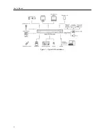
Page 10: ...User s Manual 2 Figure 1 Typical DVR installation...

Page 11: ...t RS232 Port Alarm Input Output RS485 Port Factory Reset Switch Network Port Audio In Out Power Cord Connector Your DVR can be used with either NTSC or PAL equipment NOTE You cannot mix NTSC and PAL e...

Page 12: ...mmon NC NO Relay Alarm Output The DVR can activate external devices such as buzzers or lights Connect the device to the C Common and NC Normally Closed or C and NO Normally Open connectors NC NO is a...

Page 13: ...can record audio from up to four sources Connect the audio sources to Audio In 1 Audio In 2 Audio In 3 and Audio In 4 as needed using RCA jacks Connect Audio Out to your amplifier NOTE It is the user...

Page 14: ...User s Manual 6...

Page 15: ...rently perform the same functions as those on the front panel The following describes each button and control Take a few minutes to review the descriptions You will use these to initially set up your...

Page 16: ...le shows the area that will be enlarged You can move the rectangle around using the arrow buttons Pressing the Enter button enlarges the area in rectangle In the live monitoring mode pressing and hold...

Page 17: ...such as time and date display language camera audio remote control record mode network and password Your DVR can be set up using various screens and dialog boxes Throughout the screens you will see Hi...

Page 18: ...Monitoring menu to enter the setup screen While setting up the DVR there will be many opportunities to enter names and titles When making these entries a Virtual Keyboard will appear Figure 5 Login sc...

Page 19: ...rt Do NOT remove the USB device until the DVR restarts otherwise the system upgrade will not be completed properly CAUTION The USB device must be FAT16 or FAT32 format Figure 9 Information setup scree...

Page 20: ...System menu and press the button The Date Time setup screen appears You can import saved DVR settings or export the current DVR settings To import saved DVR settings connect the USB device containing...

Page 21: ...tton Select from the three available date formats and press the button to save your selected format Highlight the first box beside Time and press the button The individual sections of the time will hi...

Page 22: ...side so that video clips can be saved on a CD RW Highlight the box in the Format column for the desired storage device and press the button You will be able to format the device for recording When sel...

Page 23: ...user out of the system first and then delete the user To add a Group highlight the Group box and press the button A virtual keyboard appears allowing you to enter the Group name System Check The user...

Page 24: ...a PC running RAS To add a User highlight the User box and press the button A virtual keyboard appears allowing you to enter the User Name Enter the name and assign the User to a Group and password Yo...

Page 25: ...Record Method Setup Select the desired recording mode from Motion Event Record Recommended Continuous Motion Event Record Continuous Record NOTE You should understand each recording mode before setti...

Page 26: ...ips Time High 5 ips Event Continuous Record Very High 30 ips High 5 ips Standard 2 5 ips Record Video Quality HVQPP High Video Quality Priority Profile SRP High Video Quality Priority Profile LRTPP L...

Page 27: ...n the error message No Device supporting UPnP displays check the NAT device supports the UPnP Port Forwarding function and the function is set to enabled DVRNS Setup DVRNS Server Enter the IP address...

Page 28: ...ow buttons to set the desired maximum bandwidth from 10Kbps to 100Mbps NOTE When limiting the network bandwidth the remote watch image on the PC running RAS or WebGuard might not be displayed properly...

Page 29: ...he NAT device via UPnP service Highlight the Port Number Setup box and press the button The Port Number Setup screen appears NOTE You will need to get the appropriate Port Numbers for each RAS and Web...

Page 30: ...f When it is On the DVR will obtain the IP address of the DNS server automatically NOTE Selecting Auto will only be enabled when the DVR is configured for DHCP network Selecting ADSL with PPPoE allows...

Page 31: ...Port and press the button Set the start port number of the RTP server obtained from your system administrator Highlight the box beside RTP End Port and press the button Set the end port number of the...

Page 32: ...ss the button to toggle between On and Off See Appendix WebGuard for detailed descriptions of the WebGuard service Highlight the box beside Port and press the button Set the port number used when acce...

Page 33: ...u can enter up to five IP addresses Highlight the box beside Retry and enter the number of times you would like the DVR to try contacting the computer You can select from 1 to 10 retries Figure 29 Cam...

Page 34: ...oduct column for the PTZ camera you wish to configure and press the button A list of PTZ devices appears Select your camera from the list and press the button You will need to connect the camera to th...

Page 35: ...ormation will be displayed on the monitor Figure 32 Alarm Out Settings setup screen The alarm output can be given its title by highlighting the box under the Title heading and pressing the button A vi...

Page 36: ...reen appears Figure 34 Display OSD setup screen Highlighting an item and pressing the button toggles that item On and Off When an item is On there is a checkmark in the box beside it The following ite...

Page 37: ...d press the button You can select from 800x600 1024x768 and 1280x1024 Highlight Full Screen and press the button Pressing the button toggles between On and Off When it is On the screen on the VGA moni...

Page 38: ...ally based on time And these sequentially recorded videos have the advantage that you can search recorded video easily even though a disk is removed from the unit However video recorded in the same ti...

Page 39: ...ng and press the button to change the time range that the scheduled recording will take place The smallest time segment you can use is 15 minutes Highlight the box under the Mode heading and press the...

Page 40: ...n the Settings column the DVR will follow the default settings See below for details NOTE Descriptions of the Record icons in the Type column are as follows Time lapse Time Alarm In Motion Video Loss...

Page 41: ...nputs associated with each alarm You can set up each input on the Alarm In screen You can turn each input On or Off by highlighting the alarm number and pressing the button Each input can be given a t...

Page 42: ...f by highlighting that item and pressing the button Highlight OK and press the button to accept your changes NOTE For the Notify action the notify item you select should be enabled in the Notification...

Page 43: ...hlighting that item and pressing the button Highlight OK and press the button to accept your changes Select Activates highlighted blocks to detect motion Clear Deactivates highlighted blocks so that t...

Page 44: ...pt your changes NOTE For the Notify action the notify item you select should be enabled in the Notification setup screen and the DVR should be registered in the RAS Remote Administration System Highli...

Page 45: ...st of PTZ presets appear Select the preset position for each PTZ camera where you want PTZ cameras to move to when the DVR detects video blind on the selected camera s input Figure 50 Video Blind Sett...

Page 46: ...oard to enter the character s that the device uses to indicate the end of a line Special characters can be created using and a capital letter e g J for NL New Line M for CR Carriage Return Refer to th...

Page 47: ...light OK and press the button to accept your changes NOTE For the Notify action the notify item you select should be enabled in the Notification setup screen and the DVR should be registered in the RA...

Page 48: ...of bad disk sectors at which you want the DVR to trigger an alert Percentage levels range from 10 to 90 Highlight the box beside Disk Almost Full Notify and press the button Select the percentage leve...

Page 49: ...setup screen on the Event menu Disk Full will be highlighted when the DVR is not in the Recycle mode and all available storage space has been used Disk Config Change will be highlighted when the DVR...

Page 50: ...User s Manual 42...

Page 51: ...nfiguration Turning on the Power Once you have installed the DVR following the instructions in Chapter 2 Installation it is ready to record Live Monitoring As soon as the DVR completes its initializat...

Page 52: ...sted prior to making any image adjustments using the DVR s controls NOTE Any image adjustments you make will be applied to both the live video on the monitors and the recorded video NOTE The Camera Me...

Page 53: ...unless a user with Covert Camera View authority logs into the system However the camera title and status icons will be displayed on the monitor If a camera is set up as Covert 2 in the Camera setup s...

Page 54: ...o display the toolbar again position the mouse pointer at the bottom of the screen Change the toolbar location by clicking the empty space on the left side of the toolbar and drag it to where you want...

Page 55: ...r Recycle Off The factory default is Recycle On It does this by recording over the oldest video once the hard disk is full Setting the DVR to Recycle Off causes it to stop recording once the hard disk...

Page 56: ...ack speed from and Pressing the button plays video forward at high speed Pressing the button again toggles the playback speed from and When in the pause mode pressing the button moves to the next imag...

Page 57: ...ing Go to the Date Time displays the Go to the Date Time screen Move the cursor over the date and time and press the Enter button You can use the Left and Right arrow buttons to highlight the year mon...

Page 58: ...rches recorded data on primary storage installed in the DVR and selecting Other searches recorded data on storage used for another DVR then installed in this DVR Exit Selecting Exit in the Search menu...

Page 59: ...ant any report of text input Highlight the box beside Record Channels and press the button You can select the cameras that you want to search for any reports of event recorded data The DVR will displa...

Page 60: ...the bottom displays the Search menu Go to Displays the first or last recorded image or searches by date and time see the previous Searching Video Go To section of this chapter for more details Clip C...

Page 61: ...press the button You will be able to select from 1 low sensitivity to 5 high sensitivity Highlight the box beside Min Blocks and press the button You will be able to set the number of sensor blocks t...

Page 62: ...s the button to save the current search option settings A virtual keyboard appears that you can use to enter the search option name Once you set your desired search conditions highlight Search and pre...

Page 63: ...eed might decrease The DVR automatically assigns a file name to the video clip However you can give the video clip file a different name Highlight the box beside File Name and press the button A virtu...

Page 64: ...computer to review the video clips Refer to the RAS manual for instructions on how to review video clips you have copied NOTE During Clip Copy you cannot shut the system down clear data on the storag...

Page 65: ...rd disk drive in Windows 98 NOTE Preparing a USB hard disk drive under Windows ME is almost identical to Windows 98 1 Connect the USB hard disk drive to your computer using the USB Cable 2 Turn on you...

Page 66: ...nt to search for Coke with a Qty Quantity of more than 1 and Hotdog with an amount totaling over 8 the following search condition can be set Search Example II 1 2 3 4 5 6 12345678901234567890123456789...

Page 67: ...ard port number default 12088 set in the Network setup screen WebGuard tab Or http DVRNS server address DVR name The DVRNS server address and the DVR name registered on the DVRNS server Or http www dv...

Page 68: ...ons Click the right mouse button on the Internet Explorer icon and select the Run as administrator option from the context menu Otherwise some functions of WebGuard might be limited NOTE There might b...

Page 69: ...cation with the remote site When the audio control panel displays click the to send audio to the connected remote site and click the button again to stop sending audio Click the to monitor live audio...

Page 70: ...ound within the time parameters The Timetable window located at the bottom displays the time information for the image of the date selected on the calendar If more than one video stream in the same ti...

Page 71: ...on the remote site to display Troubleshooting Problem Possible Solution No Power Check power cord connections Confirm that there is power at the outlet No Live Video Check camera video cable and conn...

Page 72: ...User s Manual 64 Map of Screens...

Page 73: ...Mounting failed 3 Software version error 3 No media 4 Kernel version error 4 Invalid media 100 Upgrade device mounting failed 5 File already existed 101 Package is not found 6 Not enough space 102 Ext...

Page 74: ...omposite 4 BNC Auto Terminating Monitor Output Composite 1 BNC VGA 1 VGA Audio In 4 RCA connector Audio Out 1 RCA connector Alarm Input Output Terminal blocks Ethernet Port RJ 45 RS232C Serial Port DB...

Reviews: