FALCOM A2D-JP Description Download Page 31

Description

GPS receiver

A2D–JP

Version 1.03

Side 26

In this state, a portion of the GPS receiver's RF circuitry is de-ener-
gized, the SRAMs are transitioned into their low power data reten-
tion state, and the RTC device is maintained. When the GPS recei-
ver is placed into this low power state through the use of the M_RST 
control signal, the GPS receiver will continue to draw current from 
the primary input power (PWRIN) but at a reduced level.

When the M_RST signal is subsequently asserted high by the OEM, 
RF power is re-applied, a system reset is generated, and the GPS 
receiver will return to its normal Operate mode.

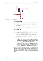
Pins 56, 53, 54 and 51: General Purpose I/O (GPIO1, GPIO2, 
GPIO3 and GPIO4)

The GPS receiver provides four General Purpose Input/Output 
(GPIO) connections that are available for use by the OEM.
These GPIO connections are digital interfaces that are OEM soft-
ware programmable as inputs or outputs.

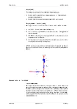
Pin 41: UTC Time Mark Pulse (TMARK)

The Time Mark output provides a one pulse-per-second (1 pps) 
signal to the OEM application processor. When the GPS receiver 
provides a valid navigation solution, the rising edge of each TMARK 
pulse is synchronized with the UTC one second epochs to within 
±300 nsec.

Pin 42: 10 kHz UTC synchronized clock

This is a 10 kHz clock waveform that is synchronized to the UTC 
TMARK pulse.
This clock signal is a positive logic, buffered CMOS level output.

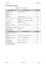
6.3.3 Serial communication signals

Symbol

Parameter

Limits (*)

Units

PWRIN 3

Main power input to the JP2 (+3,3 V DC)

3,135 to 3,465

volts

VIH (min)

Minimum high-level input voltage

0.7 x PWRIN

volts

VIH (max)

Maximum high-level input voltage

PWRIN

volts

VIL (min)

Minimum low-level input voltage

- 0,3

volts

VIL (max)

Maximum low-level input voltage

0,3 x PWRIN

volts

VOH (min)

Minimum high-level output voltage

0,8 x PWRIN

volts

VOH (max)

Maximum high-level output voltage

PWRIN

volts

Table 17: Digital signal requirements

Both the configuration and timing signals, described in the previous section, 
and the serial communication signals described below must be applied 
according to the limits shown in table 17.

Summary of Contents for A2D-JP

Page 1: ...Description Embedded GSM GPS Module A2D JP...

Page 2: ...nguages are permitted only with the prior written consent of Fal com Wireless Communications GmbH All details of FALCOM s products particularly those in catalogues in printed or other form contain dia...

Page 3: ...c equipment 8 2 8 Medical electronic equipment 8 2 9 Aircraft 8 2 10 Children 8 2 11 Blasting areas 9 2 12 Potentially explosive atmospheres 9 2 13 Non ionising radiation 9 3 Safety standards 10 4 Tec...

Page 4: ...t overview 23 6 2 1 GPS receiver architecture 23 6 2 2 Product applications 24 6 3 Technical description 24 6 3 1 General information 24 6 3 2 Hardware interface 25 6 3 2 1 Configuration and timing si...

Page 5: ...g of A2D JP 2 Figure 2 Technical drawing of A2D JP 3 Figure 3 Interface connections 12 Figure 4 Interface A 60pin connector AMP 177984 2 12 Figure 5 GPIO 1 Flash_LED 17 Figure 6 Sample application SIM...

Page 6: ...3 Side 1 Versions Version number Author Changes V 1 00 M Menz Initial version V 1 01 G Buch Chip set of RAM Flash changed GPS V 1 02 G Buch Reset chip changed GPS V 1 03 G Buch Layout of L2 R35 C2 D13...

Page 7: ...he FALCOM GSM module and the FALCOM GPS module based on the CONEXANT Zodiac 2000 chip set Information furnished herein by FALCOM GmbH is believed to be accurate and reliable However no responsibility...

Page 8: ...ion A2D JP Version 1 03 Side 3 Figure 2 Technical drawing of A2D JP 4 53 8 0 15 73 2 0 15 90 2 0 3 15 20 16 35 6 65 2 4 65 6 85 12 1 max 4 40 3 0 15 48 4 0 25 2 7 3x 5 2 8 13 3 1 65 1 7 t i e f 25 5 5...

Page 9: ...station Equipment Identity ME Mobile Equipment NMEA National Maritime Electronics Association PIN Personal Identification Number PLMN Public Land Mobile Network PRN Pseudorandom Noise Number The Ident...

Page 10: ...ETSI GSM 07 07 AT command set for GSM Mobile Equipment 3 ITU T V 25ter Serial asynchronous automatic dialling and control 4 Zodiac GPS receiver Family Designers Guide http www falcom de service downl...

Page 11: ...our modem the cellular system handling your calls controls both the radio frequency and the power level of your cellular modem The Global Positioning System uses satellite navigation an entirely new c...

Page 12: ...tact with the skin a minor burn may result Re place a damaged antenna immediately Consult your manual to see if you may change the antenna yourself If so use only a manufac turer approved antenna Othe...

Page 13: ...nt Consult the manufacturer of any personal medical devices such as pacemakers hearing aids etc to determine if they are adequately shielded from external RF energy Turn your modem OFF in health care...

Page 14: ...s grain dust or metal powders Do not transport or store flammable gas liquid or explosives in the compartment of your vehicle which contains your modem or acces sories Before using your modem in a veh...

Page 15: ...ded GMS GPS modem meets the safety standards for RF receivers and the standards and recommendations for the pro tection of public exposure to RF electromagnetic energy established by government bodies...

Page 16: ...s switched off in OFF mode 1 AT CPOF was issued and SOFT_ON was set to LOW the internal regulator is still working in idle mode base station sends at 85 dBm in transmit mode at power level 7 in transm...

Page 17: ...Description Technical data A2D JP Version 1 03 Side 12 Figure 3 Interface connections Figure 4 Interface A 60pin connector AMP 177984 2 B A C D Pin No 1 1 60...

Page 18: ...232 Ring Indicator CMOS 2 8 V out 10 DCD RS 232 Data Carrier Detect CMOS 2 8 V out 11 SOFT ON Turn phone on CMOS 2 8 V inp 12 RING PWM Ringer Interface CMOS 2 8 V out 13 TX RS 232 Transmit Data CMOS 2...

Page 19: ...47 GROUND 48 SDO 2 Serial 2 Data Output CMOS 3 3 V out 49 SDO 1 Serial 1 Data Output CMOS 3 3 V inp 50 SDI 1 Serial 1 Data Input CMOS 3 3 V out 51 WHEEL_TICK Reserved for Wheel in 52 GROUND 53 DIRECT...

Page 20: ...DCS Sensitivity 100 dBm Selectivity 200 kHz 9 dBc Selectivity 400 kHz 41 dBc Dynamic range 62 dB Intermodulation 43 dBm Co channel rejection 9 dBc Table 8 Receiver Transmitter Maximum output power EG...

Page 21: ...ui red to add serial resistance on all the lines you will use typical value from 4 7 to 10 K There are a few pins needed for the operation of the module The handling of that pins is described as follo...

Page 22: ...etwork If it flashes in a 1sec period then the module is on and a call is in progress incoming or outgoing GPIO 1 can be an input into a controller here it needs to be driven by an open collector circ...

Page 23: ...l be switched off For switching the module off the commands AT CPOF or AT CFUN 0 have to be issued If SOFT_ON is HIGH then only the RF part of the module is off but the AT command set is still working...

Page 24: ...UN 1 1 can be used This will de register the modem from the network and bring it into the state before the PIN could be entered The Flash_LED pin will shortly toggle to OFF and back to ON again to sho...

Page 25: ...modem s local flow control setting ATO Return to data mode AT VGR Tune the receive gain ATS0 n Go off hook after n th ringing signal n 1 5 AT VGT Tune the transmit gain ATS0 0 No automatic answering o...

Page 26: ...splay manufacturer ID AT CRC Select call service report AT CGMM Display model ID AT CLIP Calling line identification presenta tion AT CGMR Display version of GSM module AT CLIR Control the calling lin...

Page 27: ...ses the Zodiac 2000 chip set com po sed of two custom CONEXANT devices together with suitable memory devices Please consult CONEXANT for special information about the GPS Zodiac 2000 chip set Signal a...

Page 28: ...on with the GPS receiver is established through two asynchronous serial I O ports The GPS receiver s primary serial port outputs navigation data and accepts commands from OEM ap plication in NMEA 0183...

Page 29: ...igation 3D The GPS receiver defaults to 3 D navigation whenever at least four GPS satelli tes are being tracked In 3 D navigation the GPS receiver com putes latitude longitude altitude and time inform...

Page 30: ...Hardware interface The following paragraphs describe the basic functions allocated to the various pins on the AMP interface connector These functions are divided into three groups Configuration and t...

Page 31: ...ARK The Time Mark output provides a one pulse per second 1 pps signal to the OEM application processor When the GPS receiver provides a valid navigation solution the rising edge of each TMARK pulse is...

Page 32: ...id the default values in ROM will be used The OEM application must provide any Line Driver Line Receiver LD LR circuitry to extend the range of the interface Port Idle is nominally a CMOS logical high...

Page 33: ...de a DC power input to the SRAM and RTC devices only The GPS receiver automatically switches to the VBATT input signal when primary DC power PWRIN is removed from the board This feature is intended to...

Page 34: ...08 Frequency standard Parameter in use 1110 Power management Duty cycle in use 1117 Serial port communication Parameters in use 1130 EEPROM update Show data ID for the last write 1135 EEPROM status Sh...

Page 35: ...non volatile storage 1310 Power management control 1317 Serial port communication parame ter 1330 Message protocol control 1331 Factory calibration input For oscillator 1350 Raw DGPS RTCM SC 104 data...

Page 36: ...onexant proprietary Receiver ID Channels software version RID Recommended minimum specific GPS Data Time date position course and speed RMC Track made good and ground Speed Course and speed VTG Conexa...

Page 37: ...ogram Figure 8 The A2D JP evaluation board Figure 8 shows the A2D JP evaluation board in complete packaging i e A2D JP evaluation board A2D JP module power supply FRIWO type FW 3299 12 VDC 580 mA GPS...

Page 38: ...de 33 available So the data of both modules can be processed by your PC at the same time Thus the evaluation board offers an excellent possibility for develop ment and testing trials of your own appli...

Reviews: