


Description
GSM–modem
A2D–JP
Version 1.03
Side 17
Pin 30 (EN)
This signal is an input of the internal voltage regulator.
❐
Pull to LOW to switch the voltage regulator off (for minimum
current consumption).
❐
Pull to HIGH or leave the signal open if EN is not used.
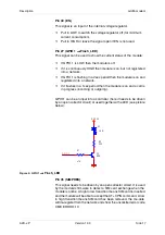
Pin 27 (GPIO 1
→
→
→
→
Flash_LED)
This signal can be used to show the current status of the module:
❐
If GPIO 1 is LOW then the module is off.
❐
If it is continuously HIGH then module is on, but not registered
into a network.
❐
If GPIO 1 is flashing in a 2sec period then the module is on and
registered into a network.
❐
If it flashes in a 1sec period then the module is on and a call is
in progress (incoming or outgoing).
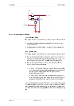
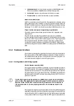
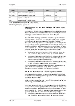
GPIO 1 can be an input into a controller (here it needs to be driven
by an open collector circuit) or used together with a LED (see picture
below):
Figure 5: GPIO 1
→
→
→
→
Flash_LED
Pin 35 (SIMPREK)
This signal needs to be driven by an open collector circuit. It is used
by the module's firmware to detect a SIM card exchange when the
module is online. A high to low transition means SIM card is inserted
and the module will be able to accept the AT+CPIN command. A low
to high transition means SIM card has been removed, the mo-dule
will de-register from the network and show the unsolicited error code
CME ERROR: 10.
V C C 3 V
R 1
4 7 K
R 2
3 3 0
Q 1
N P N
G P I O 1
D 1
L E D


