


EN
1
3
13
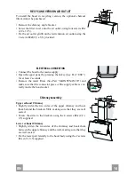
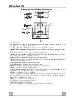
Hood body mounting
• Firstly, it is necessary to adjust the two Vr-screws of
the 11a-brackets, at minimun (B).
• Hang the hood body on the two brackets 11a.
• Connect the hood to the mains supply by means of a
bipolar switch with at least 3 mm contact gap.
• Press the “A”-key for one second (see Part USE) to
open the upper panel.
• Remove the metal filters.
• In order to align the hood it is necessary to adjust the
Vr-screws from inside the hood.
• Fasten the safety screw 11.
• Fit again the metal filters into their seats and close the
upper panel by pressing “L”-key for one second (see
Part USE).
• Disconnect the hood from the mains supply.
Attention: the upper panel stops if any barrier occurs in its
way during the panel opening or closing. To open the panel
it is enough to remove the barrier and press the key once
again.
( B )
L
A
11a
Vr
11
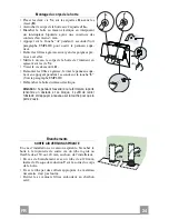
Connections
DUCTED VERSION AIR EXHAUST SYSTEM
When installing the ducted version, connect the hood to
the chimney using either a flexible or rigid pipe ø 150
or 120 mm, the choice of which is left to the installer.
• To install a ø 120 mm air exhaust connection, insert
the reducer flange 9 on the hood body outlet.
• Fix the pipe in position using sufficient pipe clamps
(not supplied).
• Remove possible charcoal filters.
ø 150
9
ø 120
Summary of Contents for Mirror WH PRO X-V A80
Page 1: ...Instructions Manual Manuel d Instructions Bedienungsanleitung Manual de instrucciones...
Page 6: ...GR 6 6 53 54 56 59 61...
Page 7: ...RU 7 7 64 65 67 70 72...
Page 8: ...SA 8 8 75 76 78 81 84...
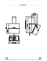
Page 11: ...EN 1 1 11 Dimensions...
Page 22: ...FR 2 2 22 Encombrement...
Page 33: ...DE 3 3 33 Platzbedarf...
Page 44: ...ES 4 4 44 Dimensiones...
Page 53: ...GR 5 3 53 I 120 mm...
Page 55: ...GR 5 5 55...
Page 57: ...GR 5 7 57 Vr 11a B 11a 3mm 1 A Vr 11 1 L B L A 11a Vr 11 o150 120 mm o120 mm 9 150 9 120...
Page 60: ...GR 6 0 60 1 5 V LR03 AAA T1 T2 T3 2 T4 2 T5 2 T6 T7 Delay 24h 2 24 T1 T6 T2 T3 T4 T5 T7...
Page 61: ...GR 6 1 61 2 G 2 1 A...
Page 62: ...GR 6 2 62 C 4 E 5 E 3 D C C G 2 1 A A B A B 20 W...
Page 63: ...GR 6 3 63...
Page 64: ...RU 6 4 64 I 120...
Page 66: ...RU 6 6 66...
Page 68: ...RU 6 8 68 Vr 11a B 2 11a 3 1 Vr 11 L 1 B L A 11a Vr 11 150 120 120 9 150 9 120...
Page 70: ...RU 7 0 70 A 1 B C D 10 I 100 24 F 30 G 2 100 200 5 I 1 L 1 3 1 F 5 B A D C E G F I H L...
Page 71: ...RU 7 1 71 1 5 LR03 AAA T1 T2 T3 2 T4 2 T5 2 T6 T7 24 2 24 T1 T6 T2 T3 T4 T5 T7...
Page 72: ...RU 7 2 72 G 2 1...
Page 73: ...RU 7 3 73 4 5 3 D G 2 1 A B 20...
Page 74: ...RU 7 4 74...
Page 75: ...SA 7 5 75 I 120...
Page 77: ...SA 7 7 77...
Page 79: ...SA 7 9 79 Vr 11 a B 11 a 3 A Vr 11 L B L A 11a Vr 11 120 150 120 9 150 9 120...
Page 81: ...SA 8 1 81 on off A B C I 10 D 24 100 3 E 30 F 100 C 200 G H on off I L F B A D C E G F I H L...
Page 82: ...SA 8 2 82 1 5 LR AAA T1 on off T2 T3 on off T4 T5 T6 T7 24 24 T1 T6 T2 T3 T4 T5 T7...
Page 83: ...SA 8 3 83 G A...
Page 84: ...SA 8 4 84 C 4 E 5 E D 3 C C G A A B A B 20...
Page 85: ...SA 8 5 85...
Page 86: ......
Page 87: ......


