


EN
1
2
12
INSTALLATION
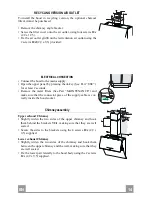
Wall drilling and bracket fixing
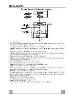
As a first step, proceed with the following drawings:
• a vertical line up to the ceiling or up to the upper limit, at the centre of the area in which the
hood is to be fitted;
• a horizontal line at a minimum 960 mm above the cooker top.
• Mark a point (1) on the horizontal line, 292 mm to the right of the vertical reference line.
• Repeat this operation on the other side, checking that the two marks are levelled.
• Mark a reference point (2) as indicated at 200 mm from the vertical reference line and 458
mm above the cooker top.
• Repeat this operation on the other side, checking that the two marks are levelled.
• Mark a reference point (3) at 743 mm above the cooker top on the vertical reference line.
• Drill at the marked points (1), using a ø 12 mm drill bit.
• Drill at the marked points (2) and (3), using a ø 8 mm drill bit.
• Insert the bracket plugs 11a into the holes (1) and tighten the screws.
• Insert plug 11 into holes (2) and (3).
• Place bracket 7.2.1 on the wall, about 1-2 mm from the ceiling or from the upper limit,
aligning the centre (notch) with the vertical reference line.
• Mark the wall at the centres of the bracket holes.
• Place the bracket 7.2.1 on the wall at X mm below the first bracket (X = height of the upper
chimney section), aligning the centre (notch) with the vertical line.
• Mark the wall at the centres of the bracket holes.
• Drill ø 8 mm holes at all the marked centre points.
• Insert the wall plugs 11 in the holes.
• Fix the brackets using the 12a screws (4,2 x 44,4) supplied with the hood.
11a
1
1
2
2
200
11
12a
11
12a
3
292 292
960
458
X
1÷2
7.2.1
368
200
743
Summary of Contents for Mirror WH PRO X-V A80
Page 1: ...Instructions Manual Manuel d Instructions Bedienungsanleitung Manual de instrucciones...
Page 6: ...GR 6 6 53 54 56 59 61...
Page 7: ...RU 7 7 64 65 67 70 72...
Page 8: ...SA 8 8 75 76 78 81 84...
Page 11: ...EN 1 1 11 Dimensions...
Page 22: ...FR 2 2 22 Encombrement...
Page 33: ...DE 3 3 33 Platzbedarf...
Page 44: ...ES 4 4 44 Dimensiones...
Page 53: ...GR 5 3 53 I 120 mm...
Page 55: ...GR 5 5 55...
Page 57: ...GR 5 7 57 Vr 11a B 11a 3mm 1 A Vr 11 1 L B L A 11a Vr 11 o150 120 mm o120 mm 9 150 9 120...
Page 60: ...GR 6 0 60 1 5 V LR03 AAA T1 T2 T3 2 T4 2 T5 2 T6 T7 Delay 24h 2 24 T1 T6 T2 T3 T4 T5 T7...
Page 61: ...GR 6 1 61 2 G 2 1 A...
Page 62: ...GR 6 2 62 C 4 E 5 E 3 D C C G 2 1 A A B A B 20 W...
Page 63: ...GR 6 3 63...
Page 64: ...RU 6 4 64 I 120...
Page 66: ...RU 6 6 66...
Page 68: ...RU 6 8 68 Vr 11a B 2 11a 3 1 Vr 11 L 1 B L A 11a Vr 11 150 120 120 9 150 9 120...
Page 70: ...RU 7 0 70 A 1 B C D 10 I 100 24 F 30 G 2 100 200 5 I 1 L 1 3 1 F 5 B A D C E G F I H L...
Page 71: ...RU 7 1 71 1 5 LR03 AAA T1 T2 T3 2 T4 2 T5 2 T6 T7 24 2 24 T1 T6 T2 T3 T4 T5 T7...
Page 72: ...RU 7 2 72 G 2 1...
Page 73: ...RU 7 3 73 4 5 3 D G 2 1 A B 20...
Page 74: ...RU 7 4 74...
Page 75: ...SA 7 5 75 I 120...
Page 77: ...SA 7 7 77...
Page 79: ...SA 7 9 79 Vr 11 a B 11 a 3 A Vr 11 L B L A 11a Vr 11 120 150 120 9 150 9 120...
Page 81: ...SA 8 1 81 on off A B C I 10 D 24 100 3 E 30 F 100 C 200 G H on off I L F B A D C E G F I H L...
Page 82: ...SA 8 2 82 1 5 LR AAA T1 on off T2 T3 on off T4 T5 T6 T7 24 24 T1 T6 T2 T3 T4 T5 T7...
Page 83: ...SA 8 3 83 G A...
Page 84: ...SA 8 4 84 C 4 E 5 E D 3 C C G A A B A B 20...
Page 85: ...SA 8 5 85...
Page 86: ......
Page 87: ......


