background image

Page | 5 


Configuring the EP104 


Before starting programming of the EP104, it is best to familiarize yourself with navigating through the menus. The 
EP104 display can show a value up to 4 digits long, or a channel number with the prefix C, d, F, L, o, P, or r followed 
by 3 digits. If an E appears followed by a 3-digit number, this is an Error message (please refer to Error Messages in 
the main manual on page 53). Please note that on first power up, the display will show EP-1 or EP-2 which is 
identifying if this a unit design for one or two motors, respectively. 

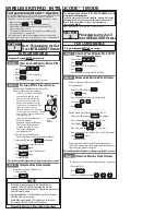
 Please study the below, which explains the process. 


Summary of Contents for DAAB EP104

Page 1: ...DAAB EP104 Quick Start Guide...

Page 2: ...ngs 8 Automatic Closing 8 EP104 Outputs and Connecting a Lock 9 Outputs 9 Wiring a Magnetic Lock to a EP104 9 Wiring a Traffic Light to a EP104 10 Common Errors and Troubleshooting 11 Troubleshooting...

Page 3: ...should now from a closed position open on Input 1 and when fully open the Start LED will begin to flash as it counts down the pause time and then automatically close barring any permanent commands or...

Page 4: ...in visual sight of the gate for commissioning purposes Fit the Gate Operator s as per the drawings provided Power and Motor Connections Connect the main power to the board and wire the motors in acco...

Page 5: ...wise fit a N C Emergency Stop Button across the terminals Photocell Circuit Default Function is Active on Closing Only Connect a Photocell as per the below or Link Terminal 28 to 29 you can also wire...

Page 6: ...channel number with the prefix C d F L o P or r followed by 3 digits If an E appears followed by a 3 digit number this is an Error message please refer to Error Messages in the main manual on page 53...

Page 7: ...likely that an Error will be generated as have not yet set the power readings If it does not move something is not wired correctly check incoming voltage motor connections first Step 4 Motor Power and...

Page 8: ...a note of the value Now press the Close Button on the board and make a note of the value 25 Set L112 value recorded from L111 when fully open 26 Set L113 value recorded from L111 when fully closed 27...

Page 9: ...if applicable to Motor 1 only 2 if applicable to Motor 2 only or 3 if applicable to both Motors Set P463 1 Set L116 degree position where Motor 1 will stop use L111 to see the reading in normal operat...

Page 10: ...d to the EP104 and wired as shown below Please ensure that the EP104 is completely powered down before installation of the output card and that the desired outputs are wired in as per the below and th...

Page 11: ...and run a separate power supply positive to the Traffic Light and you would switch the negative through the outputs as per below Magnetic Lock through Output 2 relay shown in the next page The followi...

Page 12: ...Page 11 Common Errors and Troubleshooting Troubleshooting...

Reviews: