4
ENGLISH
These instructions apply to
FAAC D700HS
model.
The D700HS automated systems automate balanced sectional
doors of single garages for residential use. They consist in an
electro-mechanical operator, an electronic control unit and
a courtesy lamp integrated in a single enbloc that, ceiling-
mounted, enables the door opening thanks to a chain or belt
transmission.
The non-reversing system guarantees the mechanical block of
the door when the motor is not operating and therefore there is
no need to install a lock; an internal and an external (optional)
manual release make it possible to move the door in the event
of a power cut or malfunction. The operator is equipped with
an electronic device that detects the presence of obstacles, if
any, preventing the door movement and avoiding any crushing
or lifting. These instructions refer to the operator with chain drive,
however, the same procedures, adjustments and application
limits also apply for the operator with belt drive.
The D700HS automated systems were designed
and built for internal use and to check the
vehicle access. Avoid any other use.
The noise emission level of the D700HS operator,
referred to the work station, is 52 dB(A).
1. DIMENSIONS
2. TECHNICAL SPECIFICATIONS
AUTOMATED SYSTEM D700HS
Model
D700HS
Power supply (V~ / 50 Hz)
230
Electric motor (Vdc)
24
Max. absorbed power (W)
440
Thrust force (N)
700
Rated Operating Time (R.O.T.)
18
min.
55 °C
Max. overall dimensions from ceiling (mm)
35 (Fig. 5)
Courtesy lamp (V~ / W)
230 / 40 max.
Courtesy lamp timing (s)
120
Carriage standard no-load speed (m/min)
12
Carriage reduced no-load speed (m/min)
3.8
Carriage decelerated speed (m/min)
1.3
Standard speed noise (dBA)
52
Deceleration travel length
Can be varied from setup
Intrinsic safety device
Class 2
Sectional door max. width (mm)
5000
Sectional door max. height (mm)
See useful travel
Sliding guide useful travel (mm)
2000 - 2600 - 3200 - 3800
Protection class
Only for internal use (IP20)
Operating ambient temperature (°C)
-20 / +55
For the dimensions of the
FAAC D700HS
operator, consult Fig. 3
and Chapter 2: Technical Specifications.
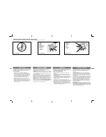
3. TOOLS, MATERIALS AND ELECTRIC PREPARATIONS
The necessary tools for installing the D700HS operator are
indicated in Fig. 1.
The necessary material for installing the D700HS operator is:
Numbers refer to Fig. 2.
- Use cables with a suitable insulation class.
- The electrical system must comply with the instructions given
in chapter “Warnings for the installer”.
- The power cable with 230V~ must be laid and connected
by a qualified installer. Close to the operator have a socket,
type 2P - 10A - 250 V~, installed.
- Lay cables in suitable tubes and prevent free cables from
entering into contact with moving parts of the automated
system and of the door.
- Separate low-voltage cable and 230V~ power cables in
different tubes.
- Prepare the electrical system in compliance with the
instructions given in chapter “Warnings for the installer”.
- After installation, make sure that no tubes or external cables
can come in contact with moving parts.
- Install the fixed command points at a minimum height of 150
cm, distant from the area involved in the door movement,
but in such a position to be checked visually.
TYPE
ø
(mm ²)
QTY.
1
Network Power Supply
ø 1,5
2
2
Operator Power
Supply
ø 1,5
2
3
Flashing lamp
ø 1
2
4
RX photocells
ø 0,5
3
5
TX photocells
ø 0,5
2
6
Key-operated selector
ø 0,5
2
7
Low-Voltage
tubes
-
-
4. DESCRIPTION
The description of the
FAAC D700HS
operator refers to Fig. 4.
Ceiling fitting
Rear door
Courtesy lamp
D700HS operator plastic cover
Rear fitting
Sliding guide
Driving carriage
Driving carriage
Door fitting bracket
Transmission unit
Front fitting and chain-tensioner
Front fitting bracket
Summary of Contents for D700HS
Page 1: ...D700HS...
Page 15: ...8 5 6 7 4...
Page 16: ...15 14 13 12 11 10 A B C 9...
Page 17: ...23 22 21 20 15 20 19 18 17 16...
Page 18: ...28 OPEN A ALTRE SICUREZZE STOP 27 26 25 24 A C B...
Page 19: ...35 34 31 32 33 30 OPEN B OPEN A RADIO SET UP 29...
Page 20: ...43 2 sec 5 sec 42 41 8 sec 40 1 sec 38 39 2 sec 5 sec 37 8 sec 36 1 sec...
Page 21: ...50 49 51 4 sec 2 sec 5 sec 48 5 sec 47 2 sec 5 sec 46 44 45 5 sec 4 sec...