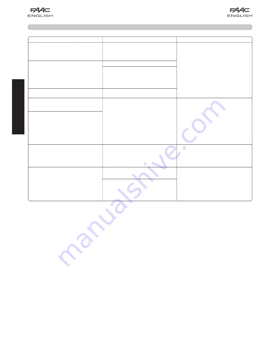
background image

17

ENGLISH

18

. TROUBLESHOOTING

Trouble

Possible causes

Solution

When the learning procedure is started, 

the SET UP LED flashes but the automated 

system does not perform any 

manoeuvre 

The STOP and FSW safety devices are 

enabled also during the learning stage. 

Non-connection or wrong connection 

prevents the operator from working

Check the LEDs’ status following the 

instructions of the “Inputs status LEDs”. 

Check the connections shown in fig. 27

The automated system does not 

perform any movement  

STOP command enabled

The automated system opens the door 

but does not close it

FSW safety devices engaged

The Fail-Safe function is enabled, but the 

NC contact of the devices connected 

to the FSW input does not open during 

test by the unit before the manoeuvre 

is started

Learning is not finished correctly and the 

SET UP LED flashes to signal a fault

The automated system frequently 

reverses motion during the opening 

and/or closing manoeuvre

-The automated system detects that 

the door movement is too difficult.

- If you are using manual adjustment of 

  force, the set thrust could be insufficient.

Check the balance of the door and 

make sure that it moves without too much 

friction. Move the door manually, using 

the rod fitting on the door, and check 

if the movement is smooth and does 

not require too much traction or thrust. 

Execute a new learning cycle. If necessary, 

vary the thrust force (if using manual 

adjustment) or start learning with a ma-

ximum thrust of 1000N.

It is difficult to release the automated 

system while the door is closed 

Too much mechanical load on the release 

system with the door closed

Run a new learning cycle and, 

when over, lighten the closing thrust, 

commanding the carriage to withdraw 

as described in  paragraph 11.2.

The SET UP LED flashes to signal a fault 

status

The learning cycle did not finish 

positively.

Run a new learning cycle

DS1’s switch No. 3 (automatic/manual 

adjustment of force) was shifted and a 

new learning cycle was not executed.

Summary of Contents for D1000

Page 1: ...D1000 D1000...

Page 2: ...ur les remarques concernant les caract ristiques ou le fonctionnement du produit Vor der Installation des Produkts sind die Anweisungen vollst ndig zu lesen Mit dem Symbol sind wichtige Anmerkungen f...

Page 3: ...board components p 10 8 3 Terminal boards and connectors p 10 8 4 DS1 Programming dip switches p 10 8 5 Operating logics p 10 9 COURTESY LIGHT p 11 10 CONNECTIONS p 11 11 PROGRAMMING p 12 11 1 Settin...

Page 4: ...install the external control devices at a height of not below 150cm clear of the door movement area but in a position enabling visual control of the area When you have finished installing we advise y...

Page 5: ...ng 16 Use of at least one indicator light e g FAACLIGHT is recommended for every system as well as a warning sign adequately secured to the frame structure in addition to the devices mentioned at poin...

Page 6: ...ccess Do not use them for any other purpose 1 DIMENSIONS 2 TECHNICAL SPECIFICATIONS AUTOMATED SYSTEM D1000 3 ANCILLARY ELECTRICAL EQUIPMENT Prepare the electric system in keeping with the instructions...

Page 7: ...ducts but do not use grease and in any event follow the manufacturer s instructions Check correct balance and if the opening mechanical stops have been installed Remove the door s existing closing mec...

Page 8: ...g guide until it is near the front terminal the one opposite the drive coupling 3 Assemble the front fitting Fig 7 ref B to the transmission unit Fig 7 ref A 4 Apply slight tension to the chain tighte...

Page 9: ...corresponding to the maximum height reached by the door during movement see Fig 4 3 Position the securing bracket of the front fitting so that the lower edge is at least 5 mm above the intersection po...

Page 10: ...5 Mark drill and secure the fitting to the door using the screws ref Fig 17 NOT supplied Fig 14 Fig 15 Fig 18 Fig 17 Fig 16 8 Lift the sliding guide until the rear fitting is at the same level as the...

Page 11: ...80 cm off the ground and cut off the excess section of rope 2 Make a knot at the end of the rope and assemble the release handle Fig 22 3 Pull the release handle down and check if the door can be move...

Page 12: ...LOCKED Closes No effect 2 No effect 1 Supply voltage V Hz 230 50 Power supply to accessories Vdc 24 Accessories max load mA 200 Operating ambient temperature C 20 55 Quick fit connector for receiver b...

Page 13: ...he input to the terminal If the photocells are not used connect the FSW input to terminal TX FSW Inputs status leds The automated system stopped and at rest is indicated in bold for each input STOP 1...

Page 14: ...rent conditions and following commands or action by the safety devices Learning can be automatic or manual In the latter case the opening and closing deceleration points can be determined However in a...

Page 15: ...UP LED starts to flash when you release the push button Start the following procedure within 4 seconds otherwise the operator will perform automatic SET UP 1 Give the 1st OPEN command the operator pe...

Page 16: ...ond and then goes OFF indicating that storage was executed 6 To add other radio controls set the same ON OFF combination used in point 1 12 2 Memory storage of radio controls SLH A Maximum of 250 code...

Page 17: ...EN A or OPEN B 5 The LED on the board relating to the channel being learned flashes for 5 sec within which time the code of another radio control must be transmitted 6 The LED lights up on steady beam...

Page 18: ...4 Fig 36 Fig 37 17 3 Safety edge CN60E The use of the safety edge with conductive element is facilitated because the control unit Fig 36 ref can be housed on board the operator Procedure Grip the rear...

Page 19: ...ently reverses motion during the opening and or closing manoeuvre The automated system detects that the door movement is too difficult If you are using manual adjustment of force thesetthrustcouldbein...

Reviews: