background image

P a g e

 | 

2


STEP 1 

Please ensure that the door is free swinging, not binding and any closers (such as surface mount, in-
head pivot closers, hinge closers) are removed prior to commencement of installation. 

STEP 2 

Depending on the type of arm being used, there will be inside the box a 1:1 Scale Mounting Template 
(See below). Please use this template for the position of the mounting holes, both for the operator 
and the arm. If for any reason, this is not available please refer to the 950N2 manual and pages 13 
through to 16 for the mounting holes positions.  

Please also use appropriate fixings for the material that you are fixing the operator to. In General, 
60mm of Softwood, 40mm of Hardwood, 10mm of Aluminium or 6mm of Steel. 

STEP 3 

Once  the  operator and  arm are  mounted to the door and header,  connect the  main power to  the 
950N2 ensure that the earth is securely connected. (See below) 
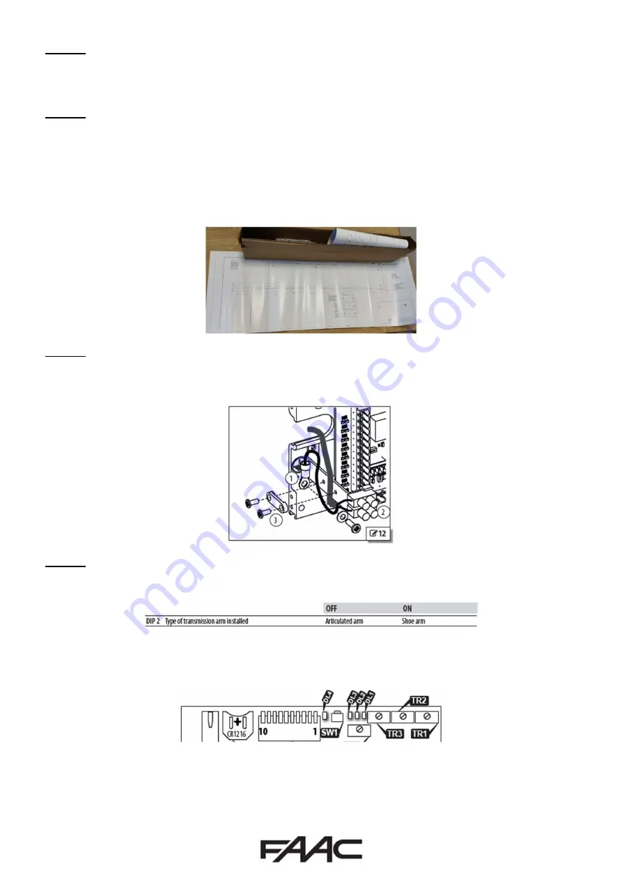
STEP 4 

Depending on the arm used, adjust DIPSWITCH “2” accordingly as per below. 


Once adjusted, DL4 on the Logic Board will illuminate “YELLOW” (See below). This is to identify that 
a change is made on the DIPSWITCH or TRIMMER banks. The changes will only take effect when SW1 
(See below) is pressed for 1.5secs on the Logic Board.  


Please note that if the KP EVO is used for Programming, DL4 will illuminate “YELLOW” but 

DO NOT


press SW1 as this will revert back to DIPSWITCH or TRIMMER setting. 


Summary of Contents for 950N2

Page 1: ...g with the Hold Open time We have included references where to find relevant wiring information for the fitting of Safety Sensors to protect the swept area of door doors as specified by specified by the Risk Assessment undertaken by the installer The installer should still familiarise themselves with the full manual and the safety information contained within available at https www faac co uk door...

Page 2: ...fixings for the material that you are fixing the operator to In General 60mm of Softwood 40mm of Hardwood 10mm of Aluminium or 6mm of Steel STEP 3 Once the operator and arm are mounted to the door and header connect the main power to the 950N2 ensure that the earth is securely connected See below STEP 4 Depending on the arm used adjust DIPSWITCH 2 accordingly as per below Once adjusted DL4 on the ...

Page 3: ...closed to fully open If using the trimmers please press SW1 on Logic board as in Step 4 At this point the door should be operational and a short across Terminals 10 11 15 or 17 and COM should trigger the automation of the door This should also illuminate DL2 DL3 DL7 or DL9 respectively STEP 7 Nearly all installations will require the use of On Door Safety Sensors be it the more basic XPB ON s XPB ...

Page 4: ...e Step 5 above for location details Please note that Factory default is in the OFF position STEP 3 Plug the KP Evo into the operator that you designate to be the SLAVE i e not receiving the opening commands Using the KP Evo go to Spanner Programming and then into Intercom see below and performing the following configuration changes Set Function to 2 Leaves Set Master Slave Nr to 2 Slave Unplug KP ...

Reviews: