background image

16

6.  START-UP

Fig. 34

6.2. 

OPENING - CLOSING DIRECTIONS

Power up the system and set the opening direction on the 
board (see Section 5.5.1).

I

f opening direction is to the RIGHT

 (

):

OPENING limit-switch LED = 

FC1

CLOSING limit-switch LED = 

FC2

If opening direction is to the LEFT


(

):

OPENING limit-switch LED = 

FC2

CLOSING limit-switch LED = 

FC1

Note: for RF chain applications the wires on Mot1 and Mot2 
(See Fig. 23) need to be reversed.
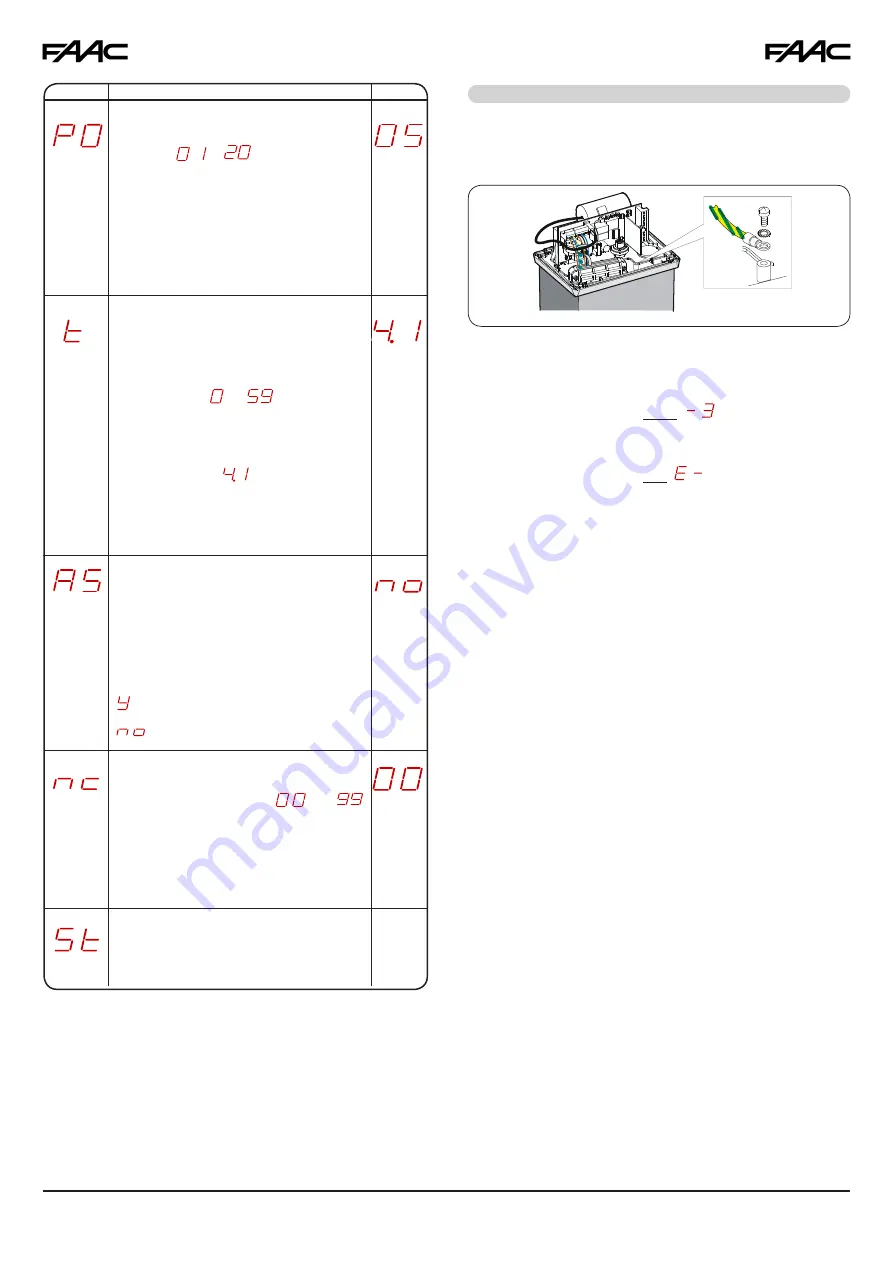
6.1. 

ELECTRIC CONNECTIONS

Make all electrical connections to the board as described in 
Section 5, including grounding the operator (Fig. 34).

6.3.  

DETERMINING STOP POINTS AT TRAVEL    

 LIMIT

The 844 operator has a limit sensor switch which, by detecting 
the transit of a reference applied to the rack, commands 
the motor to stop. The device can be magnetic (Fig. 41) or 
inductive (Fig. 42).

6.3.1.  

Magnetic Limit-Switch (MLS) 

The MLS limit-switch detects the transit of two magnets fitted 
on the side of the rack facing the operator.
Procedure for correct positioning of the two supplied magnets:

1.  Check that the operator is in manual mode (see Sec.8).
2.  Manually open the gate to within 3/4 to 2 inches of the 

travel limit mechanical stop.

3.  Fit the magnet (without removing the protective film from 

the adhesive side) on the side of the rack facing the 
operator, aligning the upper edges. Slide the magnet on 
the rack in opening direction until the relevant LED turns 
on (Fig. 22 and 41), then move the magnet forward an 
additional 1 3/4 inches.

4.  Manually close the gate to within 3/4 to 2 inches of the 

travel limit mechanical stop.

5.  Fit the magnet (without removing the protective film from 

the adhesive side) on the side of the rack facing the 
operator, aligning the upper edges. Slide the magnet on 
the rack in closing direction until the relevant LED turns 
on (Fig. 22 and 41), then move the magnet forward an 
additional 1 3/4 inches.

6.  Move the gate to its halfway travel point and relock the 

system (see Sec. 9).

7.  Find out the desired pre- and post-limit-switch decelera-

tion values (see Section 5.5.2) and run the automated 
system for at least one complete cycle.

Display 

                   Function 

Default

Note 1

:  To reset the programming default settings, check 

that the edge input is closed (SAFE LED ON), and 
simultaneously press keys 

+,  - 

and 

F

, holding them 

down for 5 seconds.

Note 2

:  Modifications of programming parameters take 

effect immediately, whereas changes are saved to 
memory only after you exit programming and return 
to normal gate status viewing. If the equipment is 
powered down before returning to status viewing, 
any modifications will be lost.

ASSISTANCE REQUEST (combined with 
next function):

If activated, at the end of countdown (see the 
next function: "Cycle Programming") it effects 
2 sec. (in addition to the value already set 
with the PF function) of pre-flashing at every 
Open pulse (job request). It can be useful to 
set scheduled maintenance jobs.

 = Active

 = Disabled

WORK TIME (time-out):

It is advisable to set a value of 5 to 10 seconds 

over the time taken by the gate to travel from 
the closing limit-switch to the opening limit-
switch and vice versa. 

Adjustable from 

 to 

 sec. in one-se-

cond steps.
Subsequently, display changes to minutes and 
tens of seconds (separated by a point) and 
time is adjusted in 10 second steps, up to a 
maximum value of 

 minutes.

Attention: the set value will not exactly 
match the motor's maximum operating 
time if decelerations are used.

PARTIAL OPENING:

You can adjust the width of partial leaf ope-
ning. from 

 to 

.

For example, with pinion Z20, partial opening 
can vary from 2' to 13'.

CYCLE PROGRAMMING:

To set countdown of system operation cycles. 
Settable (in thousands) from 

 to   


thousand cycles.

The displayed value is updated as cycles 
proceed.

GATE STATUS:

Exit from programming, save data and 
return to viewing gate status (see Section  
5.5.1.).

Summary of Contents for 844

Page 1: ...FAAC International Inc Headquarter East Coast Operations 3160 Murrell Rd Rockledge FL 32955 Tel 800 221 8278 www faacusa com FAAC International Inc West Coast Operations 357 South Acacia Avenue Fuller...

Page 2: ...inions 9 5 CONTROL BOARD 780D 10 5 1 Warnings 10 5 2 780D Technical Specifications 10 5 3 Layout And Components 10 5 4 Electric Connections 11 5 5 Programming 13 6 START UP 16 6 1 Electric Connections...

Page 3: ...located within line of sight of the gate Activation of the reset control shall not cause the operator to start 7 All warning signs and placards must be installed and easily seen within visible proxim...

Page 4: ...unreasonable use If a gate system component malfunctions disconnect the main power before attempting to repair it Do not impede the movement of the gate you may injure yourself or damage the gate sys...

Page 5: ...loading docks or other locations not intended to service the general public RESTRICTED ACCESS VEHICULAR GATE OPERATOR CLASS IV A vehicular gate operator system intended for use in guarded industrial l...

Page 6: ...he 844 gearmotor can operate non stop at 70 use frequency To ensure efficient operation operate in the work range below the curve Important The curve is obtained at a temperature of 75 F Expo sure to...

Page 7: ...wn in Fig 4 The foundation plate must be located as shown in Fig 5 right closing or Fig 6 left closing to ensure that the rack and pinion mesh correctly 2 Prepare a concrete pad as shown in Fig 7 foll...

Page 8: ...on and weld the threaded dowel nut to the gate as shown in Fig 15 4 Move the gate manually checking that the rack is resting on the pinion then weld the second and third dowel nut 5 Place another rack...

Page 9: ...between rack and pinion 4 5 INSTALLATION OF CHAIN PINIONS 3 Insert the pin g on the shaft using a hammer 4 Fit the idle transmissions bracket on the operator flange using the four screws a M5 x 12 and...

Page 10: ...installers only AC power should be supplied from a circuit breaker panel and must have its own dedicated circuit breaker This supply must include a green ground conductor Properly ground the gate oper...

Page 11: ...g after two seconds Encoder Monitors for an obstacle during gate opening and closing movements It causes immediate reversal of motion and stopping after two seconds Note For compliance with the UL325...

Page 12: ...scription of operation in the different logics Fig 26 Connection of a pair of monitored opening photocells and a monitored closing edge SAFE OPEN B A OPEN OP CL 7 9 ON XS 55 CN 60 E 1 4 OPEN EDGE XS 5...

Page 13: ...tact stops gate movement To install several STOP devices connect the N C contacts in series Fig 31 Note If STOP devices are not connected jumper the STOP and terminals Connection of two Stop N C conta...

Page 14: ...tections from the inherent entrapment protection device encoder In this status the operator will also set off the audio alarm Normal operation can only be resumed by breaking the stop circuit or reset...

Page 15: ...ovement and restart it when they are released or they reverse it immedia tely Reverse immediately to closing Restart movement on release ENCODER The encoder operates as an anti crushing device If the...

Page 16: ...1 then move the magnet forward an additional 1 3 4 inches 6 Move the gate to its halfway travel point and relock the system see Sec 9 7 Find out the desired pre and post limit switch decelera tion val...

Page 17: ...system The distance between the limit switch and the plates must be 3 16 inch LEDS ON OFF OP A Command activated Command inactive OP B Command activated Command inactive FC1 Limit switch free Limit s...

Page 18: ...screwdri ver as shown in Fig 37 Ref A To increase torque turn the screw clockwise To reduce torque turn the screw counter clockwise 3 Power up the operator and check that the torque you have just set...

Page 19: ...t least once every 6 months especially the efficiency of the safety and release devices including operator thrust force 10 1 REMOVING BOARD AND TRANSFORMER If you have to disassemble the transformer b...

Page 20: ...e s a e l e r n o d n a s k c o L g n i n e p o 2 2 r o f e s o l c o t s e s r e v e R D E K C O L 3 f a e l e h t s e s o l C t c e f f e o N d e l b a s i d N E P O t c e f f e o N t c e f f e o N...

Page 21: ...f n e p o o t s e s r e v e R G N I N E P O n o i t a r e p o s p o t S n o i t a r e p o s p o t S d e l b a s i d A N E P O t c e f f e o N 2 2 r o f e s o l c o t s e s r e v e R Tab 3 f B c i g o...

Page 22: ...t Head POS P N DESCRIPTION 17 40985115 Limit Switch Chain Version 7580375 Limit Switch Rack And Pinion Version 18 390516 Breather Plug Assembly 19 701002 Cap Scr sock hea 4X10 5931 8Gz 20 7099645 Gask...

Page 23: ...Scr sock head 5X16 8G Z 56 71707615 Side Flange 57 7094085 Gasket Lateral Flange 58 7093005 Gasket For Motor Shaft A 25407 59 7070111 Bearing 6205 25 52 15 Econ 60 7061115 Pin 8X45 Ric uni En22338 61...

Page 24: ...that the limit switch plate is not too far away from the limit switch The distance between a plate and the switch should be 3 16 in Check fuse F1 and replace it if necessary The gate opens but will n...

Page 25: ...___________________________________________________________ _________________________________________________________________________________________ __________________________________________________...

Page 26: ...___________________________________________________________ _________________________________________________________________________________________ __________________________________________________...

Page 27: ...as been subject to misuse negli gence or accident or has not been operated in accordance with FAAC International Inc s or FAAC S p A s instructions or has been operated under conditions more severe th...

Page 28: ...28 2017 FAAC International Inc All Rights Reserved Published in Jan 2017...

Reviews: