background image

4

4. INSTALLING THE AUTOMATION

4.1.

PRELIMINARY CHECKS

For safe, correct operation of the automation, make sure
that the following requirements are met:

The gate’s structure must be suitable for automation.
Take special care to ensure that the wheels are large
enough to support the full weight of the gate, that a
top runner is installed and that mechanical limit stops
are fitted to prevent the gate from coming off the
runner.

The characteristics of the ground must ensure sufficient
support for the foundation plinth.

There must be no pipes or electrical cables in the area
to be dug for installing the foundation plinth.

If the gear motor is located in a vehicle transit area, it
is a good idea to provide protection against accidental
collisions.

Check that the gear motor has an efficient earth
connection.

4.2.

INSTALLING THE BASE PLATE

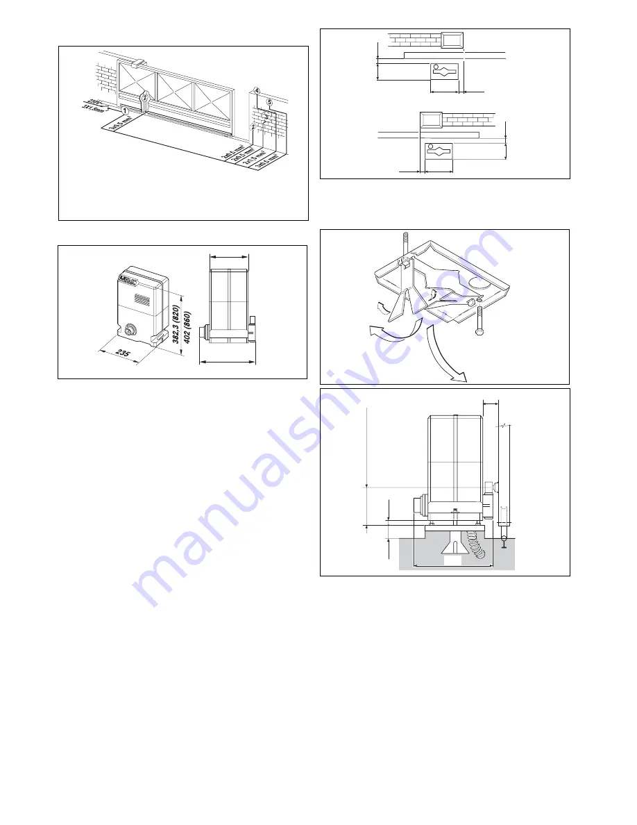
1) The base plate must be positioned as shown in Fig. 4

(right-handed closure) or Fig. 5 (left-handed closure) to
ensure that the pinion and rack mesh correctly.

N.B.:

 It is advisable to install the base plate on a concrete

base raised about 50 mm from the ground (Fig. 7).

2) Assemble the foundation plate as shown in Fig. 6.

3) Prepare a foundation plinth as shown in Fig. 8 and install

the base plate providing one or more conduits for
electrical cables. Use a level to check that the plate is
perfectly horizontal and wait for the cement to set.

4) Set up the electrical cables for connection to the

accessories and the electricity supply as described in
section 2. For ease of connection, ensure that the
cables protrude by about 45 cm from the hole in the
base plate.

820/860 operator with
826 MPS control unit

Photocells

Key switch

Flashing light

Radio receiver

Fig. 2

3. DIMENSIONS

221,2

140

Fig. 3

Values are expressed in mm.

40

165

40

165

235

235

0

¸

50

0

¸

50

Fig. 4

Fig. 6

4.3.

MECHANICAL  INSTALLATION

1) With the aid of a Teflon hammer insert the adjustable

feet into the hexagonal holes under the base of the
gear motor as shown in Fig. 9.

2) Remove the casing and position the gear motor on the

foundation plate, threading the electrical cables into
the conduit in the operator body.

3) Adjust the height of the feet and the distance from the

gate as shown in Fig. 7.

4) Secure the gear motor onto the base plate using the

two nuts and the plates provided as shown in Fig. 10.

5) Set up the operator for manual operation as described

in section 6.

6) Remove the breather screw as shown in Fig. 11 and

keep it in a safe place.

13

53

221,2

50

Z20 131 mm (820)

Z16 123 mm (860)

Fig. 7

2. ELECTRICAL SET-UP (standard system)

Fig. 5

Summary of Contents for 820

Page 1: ...Leading the way Installation Manual 820 860 Leading the way Sliding Gate System Leading the way...

Page 2: ...nt amendments 91 368 EEC 93 44 EEC and 93 68 EEC complieswiththeessentialsafetyrequirementsinthefollowingEECDirectives 73 23 EEC and subsequent amendment 93 68 EEC 89 336 EEC and subsequent amendments...

Page 3: ...provided for the installation with an opening distance of the contacts of 3 mm or more Alternatively use a 6A thermomagnetic breaker with multi pole switching 13 Ensure that there is a differential s...

Page 4: ...tial opening length 1 60 m 1 20 m Cooling self ventilated Clutch single disc in oil bath Housing treatment cataphoresis Casing painting polyester RAL 7042 Control unit 826 MPS incorporated Limit switc...

Page 5: ...ndation plinth as shown in Fig 8 and install the base plate providing one or more conduits for electrical cables Use a level to check that the plate is perfectly horizontal and wait for the cement to...

Page 6: ...ate Drill a 6 5 mm diameter hole and thread using 8 mm screw taps Tighten the bolt 4 Slide the gate manually making sure that the rack rests on the pinion and repeat the operations of point 3 5 Place...

Page 7: ...6 5 4 3 1 4 5 2 MODEL 820 EMC RF 860 MC RF figs 20 21 Insert the elastic pin 7 in the shaft with the aid of a hammer Fit the chain pinion on the shaft by matching up the pinion seats with the elastic...

Page 8: ...the 230 Vac terminals to which the flashing light must be connected 5 2 8 230 V MAINS SUPPLY terminals 13 14 These are the terminals to which the 230 Vac electricity supply must be connected Connect t...

Page 9: ...recloses 2 STOP no effect stops counting stops stops no effect SAFETY no effect recloses after 5 s stops and inverts motion when disengaged 2 no effect no effect TABLE 8 LOGIC A2 AUTOMATIC LOGIC S1 I...

Page 10: ...be positioned to ON for closure to left and OFF for closure to right The positions of dipswitches SW4 SW5 and SW6 have no effect 3 Move the gate manually to its mid travel position 4 Switch on the ele...

Page 11: ...by losing the centre scale position of the ADL the following steps must be carried out to restore the start condition 1 Release the operator 2 Slide the gate manually to the mid travel position 3 Remo...

Page 12: ...11 Fig 29 Fig 30 1 2 A B Fig 32 Fig 31 OIL...

Page 13: ...n has been selected a second impulse must be sent to reclose the gate An opening impulse send while the gate is reclosing causes it to change direction of movement A stop command if available stops mo...

Page 14: ...for either technical or commercial reasons at any time and without revising the present publication FAAC UK Limited 6 Hamilton Close Houndmills Estate Basingstoke RG21 6YT Telephone 01256 318100 Fax 0...

Reviews: