


12
•
Install a length of appropriately sized pipe
between the splined collar of the operator and
the gate leaf shoe.
•
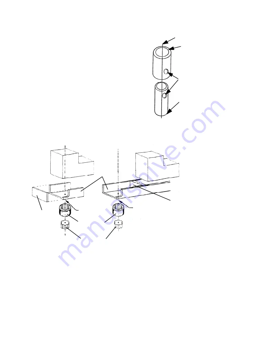
Construct a shear-pin assembly to
accommodate the extra vertical distance. The
assembly is welded to the bottom of the gate or
gate leaf shoe on one end and to the sleeve for
the splined collar on the other end (see Figures
8 and 9). Such an assembly requires a gate with
two hinges and also protects the pinion and
splined shaft in the event something hits the
gate with great force.
Installing the gate leaf shoe involves making the gate
leaf shoe, positioning it, and welding it to the splined
collar.
The gate leaf shoe is designed to carry the weight of the
gate leaf and transfer the weight to the splined shaft of
the pinion.
Weld this end of this pipe to
the bottom of the gate leaf
shoe, being certain you have
aligned the axes of rotation.
This 2 in. pipe (schedule 160)
has an inside diameter of 1.689 in.
Weld this end of this pipe to the
sleeve
for the splined shaft (do
not
weld anything to the splined shaft
itself). This 1 1/4 in. pipe (schedule
160) has an outside diameter of
1.660 in.
Axis of rotation of the gate leaf
Bolt or shear pin goes
through these holes and
the holes on the opposite
sides of the pipes.
Figure 8. A sample shear-pin assembly
Axis of rotation
within body of
gate leaf
Axis of rotation
outside body of
gate leaf
Splined shaft
Splined shaft
sleeve
U-shaped
section of
gate leaf
shoe
Vertical
section
Gate leaf
Gate leaf
Vertical
section
Note:
The gate's axis of rotation may fall within or outside the body of the gate leaf.
Figure 9. Parts of the gate leaf shoe
The shoe is made of a U-shaped section and a vertical
section (see Figure 9). Later you will weld the bottom of
the U-shaped section to the sleeve for the splined shaft
(or to the shear-pin assembly, which is welded to the
splined collar).
Since the gate leaf shoe holds the gate leaf, both
sections must be made of steel at least 1/4 in.
(0.6 cm) thick. The U-shaped section of the shoe must
be a minimum of 5 3/4 in. (2.1 cm) long and must be as
wide as the gate leaf is thick and must fit as tightly as
possible to minimize leaf movement within the shoe
(see Figure 10).
Construct the U-shaped section of the shoe and verify
that it fits around the gate leaf. Position the U-shaped
section over the splined shaft so that the leaf's axis of
rotation will fall within the minimum dimensions shown
in Figure 10.
On the U-shaped section of the shoe, mark the position
for the leaf's axis of rotation. Next, drill a pilot hole in
the U-shaped section to mark the axis of rotation point
Summary of Contents for 760
Page 20: ...20 Figure 22 Common accessories wired to 450 MPS...
Page 28: ......
Page 29: ...UL strain relief kit 2167A 710914 710915 709020002 703930...
Page 30: ......


