11
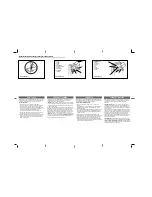
Final Welding:
After spot welding all rack sections,
move the gate from the fully closed to the fully open
position several times. Make sure that the rack runs
smoothly along the center of the pinion. If the rack and
pinion operate smoothly, finish welding the spacers to
the gate.
Again, ensure smooth gate movement and then
securely tighten the rack mounting bolts in the spacers.
Remove the spot welds and shims from under the
mounting brackets. Secure the operator to the
foundation plate by welding the operator mounting
brackets to the plate.
Connecting the
Electrical Power
WARNING!
Turn the main power off before you
make any electrical connections or set any
switches on the control panel.
The installer is responsible for providing a power
cable (with ground protected by a circuit breaker) from
the main 220 VAC power source to the operator (see
Fig. 11). All wiring should conform to applicable
electrical codes, and all wiring and fittings should be
weatherproof and/or suitable for burial.
(120mm)
1 3/8 in.
4 3/4 in.
(35mm)
Figure 7. Mounting the rack and pinion
operator
1/16 in.
(0.15 cm)
Figure 8. Spot weld the mounting brackets to
the foundation plate
Gate
Spacer
Bolt/Washer
Rack
Figure 9. Installing the rack, top view
Figure 10. Use an upside down piece of rack
to align the rack before welding
Caution:
The operator is grounded only be the
grounded circuit the installer provides.
Connecting the electrical power to the operator
consists of simply connecting the 220-V power source
to the 746 MPS control panel. The motor and capacitor
have been connected to the control panel terminal
blocks by the factory.
Connect the main 220-VAC input power to the
terminals labeled L and N (see Fig. 12 and 13) on
terminal block J7. Do not turn on the main power yet.
Connect all reversing devices in series to terminals 4
and 1. To operate, they must be normally closed. If no
reversing devices are installed, then you must install a
jumper between terminals 4 and 1 for the operator to
work properly.
Connect all stop devices in series to terminals 1 and 3.
To operate, they must be normally closed. If no stop
device is installed, then you must install a jumper
between terminals 1 and 3 for the operator to work
properly.
Connect all activating (input signal) devices in parallel
to terminals 1 and 2 (you
must
install at least one
activating device). Each device must be normally open
to activate the gate. An activating device momentarily
closes the switch to activate the operator.
Summary of Contents for 746 ER CAT
Page 18: ...18 ...