background image

15

ENGLISH

ENGLISH

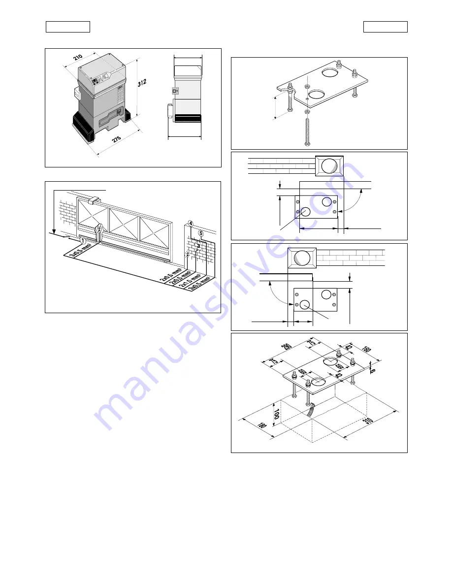
Fig. 3

2. DIMENSIONS

Fig. 2

Values are expressed in mm.

3. ELECTRICAL SET-UP (standard system)

4. INSTALLING THE AUTOMATION

4.1.

PRELIMINARY CHECKS

For safe, correct operation of the automation, make sure that
the following requirements are met:

The gate’s structure must be suitable for automation. Take
special care to ensure that the wheels are large enough to
support the full weight of the gate, that a top runner is
installed and that physical limit stops are fitted to prevent
the gate from coming off the runner.

The characteristics of the ground must ensure sufficient
support for the foundation plinth.

There must be no pipes or electrical cables in the area to be
dug for installing the foundation plinth.

If the gear motor is located in a vehicle transit area, it is
advisable to provide protection against accidental colli-
sions.

Check that there is an efficient ground point for the gear
motor connection.

4.2.

INSTALLING THE BASE PLATE

1) Assemble the base plate as shown in Fig.4.
2) The base plate must be positioned as shown in Fig. 5 (right-

handed closure) or Fig. 6 (left-handed closure) to ensure
that the pinion and rack mesh correctly.

3) Prepare a foundation plinth as shown in Fig. 7 and install the

base plate providing one or more conduits for electrical
cables. Use a level to check that the plate is perfectly
horizontal and wait for the cement to set.

4) Lay the electrical cables for connection to the accessories

and the electricity supply as shown in Fig. 3. For ease of

connection, ensure that the cables protrude by about
40 cm from the hole in the base plate (Figs. 5-6 ref.

1

).

Fig. 7

Fig. 4

Fig. 5

Fig. 6

155

191

230V~ 3x1,5 mm

2

63

225

90

°

49

0

÷

50

49

0

÷

50

155

90

°

a

746 operator with
746 MPS control unit

b

Photocells

c

Key switch

d

Flashing light

e

Radio receiver

1

1

1

1

1

1

1

1

1

1

4.3.

MECHANICAL  INSTALLATION

1) Fix the angle bars and the vibration dampers to the opera-

tor as shown in Fig. 8.

2) Open the cover of the operator by unscrewing the 4

retaining screws.

3) Fix the operator to the base plate using the nuts and

washers supplied (Fig. 9).
During this operation, route the cables through the conduit
in the lower half of the operator (Fig. 10).
To access the  electronic equipment, route  the  cables
through the holes provided using the  grommets supplied.

4) Adjust the height of the feet and the distance from the

gate as shown in Fig. 11.

Summary of Contents for 746 ER CAT

Page 1: ...TIF I C A T A UNI EN ISO 9001 085 746 746 MPS 746 746 MPS ist umweltfreundlich 100 Altpapier pour la nature papier recycl 100 for nature recycled paper 100 per la natura carta riciclata 100 para la na...

Page 2: ...resentepublicaci n todaslasmodificaciones que considere oportunas para el perfeccionamiento t cnico o para cualquier otro tipo de exigencia de car cter constructivo o comercial FAAC S p A Via Benini 1...

Page 3: ...bsequent amendments 91 368 EEC 93 44 EEC and 93 68 EEC complieswiththeessentialsafetyrequirementsinthefollowingEECDirectives 73 23 EEC and subsequent amendment 93 68 EEC 89 336 EEC and subsequent amen...

Page 4: ...automation with a contact opening distance of 3 mm or more We recommend the use of a 6A thermal magnetic circuit breaker with multi pole switching 13 Ensure that a residual current device with a trip...

Page 5: ...sk in oil bath Housing treatment cataphoresis Control unit 746 MPS Limit switches inductive with stop plates Gear motor dimensions LxHxD mm see Fig 2 Electric motor technical specifications Motor spee...

Page 6: ...r Fig 6 left handed closure to ensure that the pinion and rack mesh correctly 3 Prepare a foundation plinth as shown in Fig 7 and install the base plate providing one or more conduits for electrical c...

Page 7: ...rack to set the teeth of the two elements in phase as shown in Fig 17 6 Open the gate manually and weld the three threaded bushes Proceed in this manner until the rack covers the entire length of the...

Page 8: ...nsure correct meshing with the pinion Check manually that the gate reaches the mechanical travel lim its correctly and that it does not encounter friction during its travel Do not use grease or other...

Page 9: ...otor 24Vdc power supply for accessories pause time 5 10 30 120 sec Programming logic automatic A1 A2 semiautomatic E1 E2 pre flashing Motor braking adjustable by trimmer Safety timing 255 sec 5 1 2 74...

Page 10: ...are to be installed place a jumper across this input and the common terminal terminal 1or 5 6 24Vdc accessories power supply positive The maximum load of the accessories is 360mA To calculate power dr...

Page 11: ...rating logics There are four operating logics available A1 Automatic A2 Automatic Plus E1 Semi automatic E2 Semi automatic Plus Operation of the different logics is described in tables 5 6 7 8 Pause t...

Page 12: ...damaging the operator and or interruptions to service leave a distance of at least 2 cm from physical travel stops of the gate 5 6 TORQUE ADJUSTMENT The 746 automation system is equipped with an anti...

Page 13: ...turn off the electricity supply to the system before relocking the operator 1 Close the release lever 2 Turn the key anticlockwise 3 Remove the key and close the lock cover 4 Move the gate until the...

Page 14: ...a remote control or other suitable control device the control unit will start the motor to move the gate to the open position If automatic operation has been selected sending an impulse causes the gat...

Reviews: