11
8.1 OIL LEVEL CHECK
Make sure the operator is perfectly level, powered off and
that the piston is fully retracted (gate in the open position).
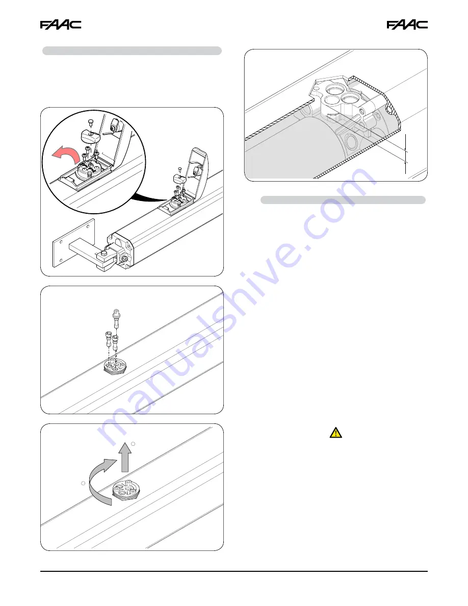
• Unlock the manual release cover and hinge it open
• Remove the red knob after removing the screw (Figure 18)
• The remove the 3 T20 security screws that are below the
red knob (Figure 18)
• Grab the manual release from both ends and gently rock
it while pulling up.
• Make sure to remove the o-ring that fits between the
manual release and the body of the operator
• Set the parts on a clean towel/location
• Next remove the 3 extensions grabbing them with plyers
and pulling straight up (Figure 19)
• Now rotate the collar (silver in color) clockwise by hand
and then lift straight up (Figure 20). It’s very important to
not use tools or pry on this piece
• Now look into the body of the machine and to the left,
the fluid should be up to the center of the tie rod (top for
400 standard or center for 400 EG when the piston is fully
retracted)
• The fluid should be 5/16” to 3/8” from the top of the valve
body as shown in Figure 21
• If the unit is low pour fluid in here until it reaches the target
level. If you overfill the unit it will come out the breather
hole in the rear flange.
• USE ONLY FAAC HP OIL
• Re-assembly the parts in reverse order making sure the
o-rings and surfaces are clear of debri
8 MAINTENANCE AND REPAIRS
Periodically check for correct adjustment of the anti-crushing
safety device and the effectiveness of the release system to
allow manual operation.
Safety devices installed on the system must be checked every
6 months.
REPAIRS
For repairs, contact FAAC’s authorized repair centers.
2
1
Figure 19
Figure 20
Figure 21
Figure 18
5/16”~3/8”


