background image

11

ENGLISH

ENGLISH

Fig.10

with no stiff points and that it stops on the phisical  travel stops.

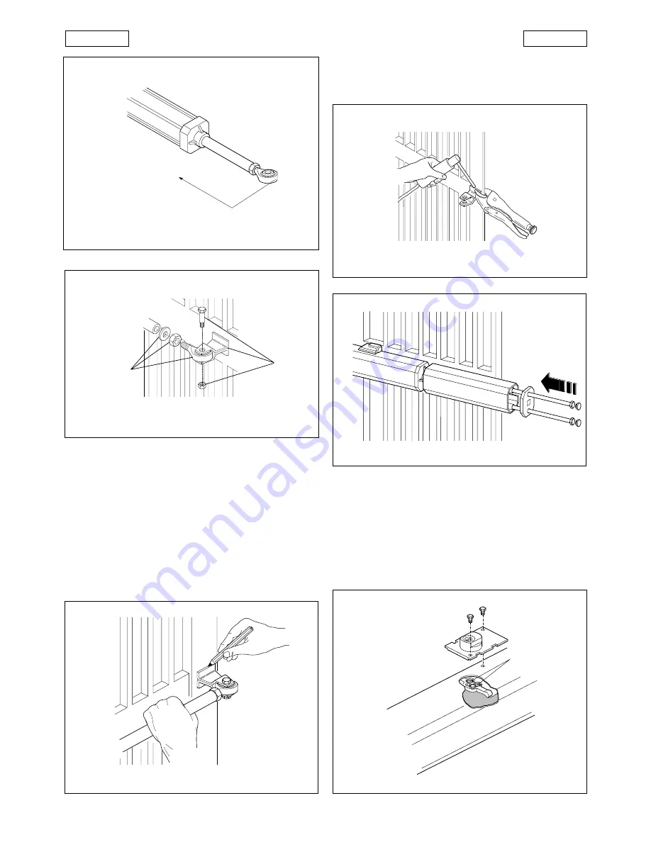
11) Completely weld the front bracket to the leaf. To weld,

detach the operator temporarily  from the bracket  to prevent
any waste material from damaging it (Fig. 8).

N.B

.:

1) Grease all pivots on brackets
2) If welding is not possible, the front and rear bracket

plates are also designed for  fixing by screws and
screw anchors.

12) Fit the cover on the operator as shown in Fig. 9. Fit the  cable

sheath (3, Fig. 11).

13) Repeat the above operations to install the second operator.

14) Make the electrical connections of the electronic control unit

following the instructions provided.

4.

START-UP

Fig. 7

Fig. 7

Fig. 9

4.1.

ANTI-CRUSHING SYSTEM ADJUSTMENT

The 400 automation is equipped with an anti-crushing system
which limits the torque applied by the operator  when the gate
leaf encounters an obstacle during its movement.
When the obstacle is removed, the gate proceeds until the set
operation time is complete.
To adjust the intervention threshold of the anti-crushing system,
it is first necessary to remove the release unit (Fig. 10).

Fig. 9

By-pass

Fig. 5

5 mm

Fig. 8

Fig. 6

a

b

Summary of Contents for 400 CBAC lungo

Page 1: ...C ERME T A Z I E N D A C E R TIF I C A T A UNI EN ISO 9001 085 400 400...

Page 2: ...al d a la presente publicaci n todas las modificaciones que considere oportunas para el perfeccionamiento t cnico o para cualquier otro tipo de exigencia de car cter constructivo o comercial FAAC S p...

Page 3: ...e 89 392 EEC and subsequent amendments 91 368 EEC 93 44 EEC and 93 68 EEC complieswiththeessentialsafetyrequirementsinthefollowingEECDirectives 73 23 EEC and subsequent amendment 93 68 EEC 89 336 EEC...

Page 4: ...on the supply line to the automation with a contact opening distance of 3 mm or more We recommend the use of a 6A thermal magnetic circuit breaker with multi pole switching 13 Ensure that a residual...

Page 5: ...n IP 55 Max thrust traction force daN 620 620 620 775 465 465 465 Rod stroke mm 260 260 260 260 260 380 380 Rod speed cm s 1 1 1 0 75 1 5 1 5 1 5 Operator weight Kg 8 6 8 6 8 6 8 6 8 6 10 10 Duty cycl...

Page 6: ...e nut provided 4 Release the operator see paragraph 5 5 Extend the rod to the end of its stroke and then retract it by Table 2 INSTALLATIONDIMENSIONS about 5 mm Fig 5 6 Lock the operator see paragraph...

Page 7: ...sheath 3 Fig 11 13 Repeattheaboveoperationstoinstallthesecondoperator 14 Maketheelectricalconnectionsoftheelectroniccontrolunit followingtheinstructionsprovided 4 START UP Fig 7 Fig 7 Fig 9 4 1 ANTI...

Page 8: ...tion on the side of the operator Fig 12 Carefullycheckoperationoftheoperatorandalltheconnected accessories especiallythesafetydevices Give thecustomerthe Userguide anddemonstratehowtouse the operator...

Page 9: ...tted with one or more electric locks to ensure mechanical locking of the gate leaves The FAAC 400 can automate gate leaves up to 7 m in length depending on the model The operators are controlled by an...

Reviews: