background image

VIPRION LCD Panel

Platform Guide: VIPRION

®

3 - 3

About the LCD menus

To use the LCD menus, you must first put the LCD panel in Menu mode. To 
put the LCD panel in Menu mode, press the 

X

 button. 

After you put the LCD panel in Menu mode, use the Left Arrow, Right 
Arrow, Up Arrow, and Down Arrow buttons to select menu options. There 
are three menus:

• Options

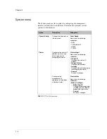
• System

• Screens

Options menu

The Options menu provides options for adjusting the display properties of 
the LCD panel.

Option

Description

Heartbeat

Turns on (checked) or off (unchecked) the heartbeat 
panel on the LCD. This heartbeat does not affect the 
failover mechanism of the system.

Backlight

Controls the backlight for the LCD panel.

Contrast

Sets the contrast of the LCD display.

On Brightness

Adjusts the LCD panel backlight brightness.

Off Brightness

Controls the brightness of the LCD panel when the 
backlight is off.

Table 3.1  

The Options menu 

Summary of Contents for Viprion

Page 1: ...Platform Guide VIPRION MAN 0311 00 ...

Page 2: ......

Page 3: ...on Module WOM WebAccelerator WA and ZoneRunner are trademarks or service marks of F5 Networks Inc in the U S and other countries and may not be used without F5 s express written consent All other product and company names herein may be trademarks of their respective owners Export Regulation Notice This product may include cryptographic software Under the Export Administration Act the United States...

Page 4: ...ation Technology products at the time of manufacture VCCI Class A Compliance This is a Class A product In a domestic environment this product may cause radio interference in which case the user may be required to take corrective actions The power cables included with this platform are designed for use solely with this platform ...

Page 5: ...Table of Contents ...

Page 6: ......

Page 7: ...figuration and mixed clusters 2 3 3 VIPRION LCD Panel About the LCD panel 3 1 Using LCD panel functionality 3 2 Pausing on a screen 3 2 Accessing LCD menus 3 2 Clearing alerts 3 2 About the LCD menus 3 3 Options menu 3 3 System menu 3 4 Screens menu 3 5 About cluster management 3 6 Configuring clusters through the LCD menu 3 6 Configuring cluster members 3 8 4 VIPRION LEDs and Interfaces About LED...

Page 8: ...consumption 6 7 NEBS information 6 7 7 Platform Airflow Platform airflow information 7 1 Airflow for VIPRION platforms 7 1 8 Environmental Guidelines for the VIPRION Platform Environmental requirements 8 1 General environmental guidelines 8 1 Guidelines for AC powered equipment 8 2 Guidelines for DC powered equipment 8 2 9 Platform Specifications General specifications for system features 9 1 AC p...

Page 9: ...1 The VIPRION Platform About the VIPRION platform Getting started with the VIPRION platform Technical support resources ...

Page 10: ......

Page 11: ...platform Everything from the blades to the power supplies the fan tray to the LCD panel is available for you to add remove or change as needed The VIPRION platform is highly extensible and designed to be easy to implement however having some familiarity with the components of the VIPRION platform can ensure that you install and integrate the platform successfully and effectively Note If you have n...

Page 12: ...ly One of the most powerful features of the VIPRION platform is that you can add remove or change any or all of the essential components of the platform These components include blades power supplies the fan tray the LCD panel and the System ID card This configuration allows for an extremely robust and flexible system that can manage large amounts of application traffic and remain operational even...

Page 13: ...nstalled Blanks must be installed in all unused slots as they help ensure proper airflow within the chassis and EMC compliance of the unit 1 Compression screw 2 Indicator LEDs 3 Management port 4 USB ports 5 Console port 6 Hard wired failover port 7 XFP ports 8 10 100 1000 interfaces 9 SFP ports Figure 1 2 Front view of the PB100 blade 1 Compression screw 2 Indicator LEDs 3 Management port 4 USB p...

Page 14: ...About VIPRION platform installation on page 2 1 Understand the environmental guidelines For more information see Environmental requirements on page 8 1 The VIPRION platform comes with the hardware that you need for installation However you must provide standard peripheral hardware such as a serial terminal if you want to administer the VIPRION platform directly Components provided with the VIPRION...

Page 15: ...ices you select must be compatible with the network interface cards installed in the VIPRION platform Ethernet requires either a 10 Mbps or 100 Mbps hub or switch Gigabit Ethernet requires a compatible Gigabit Ethernet switch 10 Gigabit Ethernet requires a compatible 10 Gigabit Ethernet switch You can use an external USB CD DVD ROM drive or a USB compact flash drive that is compatible with the sys...

Page 16: ... Welcome screen in the Configuration utility contains links to many useful web sites and resources including The F5 Networks Technical Support web site The F5 Solution Center The F5 DevCentral web site Plug ins SNMP MIBs and SSH clients F5 Networks Technical Support web site The F5 Networks Technical Support web site https support f5 com provides the latest documentation for F5 products including ...

Page 17: ...2 VIPRION Platform Installation About VIPRION platform installation PB100 and PB200 blade compatibility ...

Page 18: ......

Page 19: ...ING At least two people are required to install the VIPRION platform into a rack General recommendations for installing a chassis in a rack Although not required a 1U space between chassis makes it easier for you to remove the chassis from the rack in the event that the unit requires service A 1U space between units also provides additional cable routing options We recommend 100 mm spacing from th...

Page 20: ...nstalled indicating that the blade is running the wrong software version The software installation status also displays an error for the PB200 blade slot Earlier BIG IP software versions may display in the Configuration utility but you will not be able to install them to the PB200 blade You receive an installation error message if you attempt to install an earlier version of the BIG IP software If...

Page 21: ...ixed clusters If you replace a PB100 blade with a PB200 blade in a cluster that uses one or more trunks across the blades you must adjust the trunk configuration to match the desired PB200 external interfaces For example if your trunk uses 10G ports interface 1 1 on a PB100 blade is 10G and interface 2 1 is 10G on a PB200 blade For information on configuring a trunk see the TMOS Management Guide f...

Page 22: ...Chapter 2 2 4 ...

Page 23: ...3 VIPRION LCD Panel About the LCD panel Using LCD panel functionality About the LCD menus About cluster management ...

Page 24: ......

Page 25: ...atures on the system The following menus are available on the LCD panel Options menu Use the Options menu to configure the display properties of the LCD panel System menu Use the System menu to manage the clusters and blades that are a part of the chassis configuration Screens menu Use the Screens menu to set up the informational screens you would like the LCD panel to display Figure 3 1 Front vie...

Page 26: ...ate mode changes the screen displayed on the LCD panel every four seconds Accessing LCD menus Press the X button to put the LCD component in Menu mode to access the menus The buttons Left Arrow Right Arrow Up Arrow and Down Arrow are functional only when the LCD panel is in Menu mode For more information about using the LCD menus see About the LCD menus on page 3 3 Clearing alerts Press the Check ...

Page 27: ...s System Screens Options menu The Options menu provides options for adjusting the display properties of the LCD panel Option Description Heartbeat Turns on checked or off unchecked the heartbeat panel on the LCD This heartbeat does not affect the failover mechanism of the system Backlight Controls the backlight for the LCD panel Contrast Sets the contrast of the LCD display On Brightness Adjusts t...

Page 28: ...the cluster IP address netmask and default gateway for managing the cluster Cluster Mgmt Select from the following suboptions Cluster IP Configure the cluster IP address Cluster IP Mask Configure the netmask Gateway Configure the default gateway for managing the cluster Commit Save your changes Configures the management IP addresses of the blades within the cluster Cluster Mbrs Select from the fol...

Page 29: ...the system You can use the Check button to place a check mark next to the name of the screens you would like to display when the screens cycle Option Description DateScreen Shows the date and time InfoScreen Displays the information screen menu VersionScreen Shows the product version information Table 3 3 The Screens menu ...

Page 30: ...cluster related settings and use the Commit option to save all settings at once To configure the cluster IP address 1 Press the X button to access the LCD panel menus 2 Use the arrow keys to select the System menu and press the Check button 3 Use the arrow keys to select Cluster and press the Check button 4 Use the arrow keys to select Cluster Mgmt and press the Check button 5 Use the arrow keys t...

Page 31: ... keys to select the Commit option and press the Check button The system saves the new subnet mask for the cluster To configure the default gateway for the cluster 1 Press the X button to access the LCD panel menus 2 Use the arrow keys to select the System menu and press the Check button 3 Use the arrow keys to select Cluster and press the Check button 4 Use the arrow keys to select Cluster Mgmt an...

Page 32: ...panel menus 2 Use the arrow keys to select the System menu and press the Check button 3 Use the arrow keys to select Cluster and press the Check button 4 Use the arrow keys to select Cluster Mbrs and press the Check button 5 Use the arrow keys to select the appropriate blade Blade 1 4 Mgmt and press the Check button 6 Use the arrow keys to select Blade Mgmt IP and press the Check button The LCD pa...

Page 33: ...4 VIPRION LEDs and Interfaces About LED behavior About platform interfaces ...

Page 34: ......

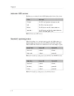
Page 35: ... a power supply connected off The chassis front panel has one LED per power supply There are eight power supply LEDs however only the first four are functional in the four slot chassis Status Reports the overall state of the chassis functional green or experiencing errors yellow Alarm Reports both blade and chassis alarms If a blade indicates an alarm condition the chassis Alarm LED mirrors that s...

Page 36: ...oes not display any color Solid The LED is lit and does not blink Blinking The LED turns on and off at a regular frequency Intermittent The LED turns on and off with an irregular frequency and may sometimes appear solid Table 4 3 Indicator LED actions System State Alarm LED Status LED Power is off off none off none Active mode off none green solid Table 4 4 Standard operating states of the LEDs on...

Page 37: ...nfig user_alert conf file to add new alerts The etc alertd alert conf defines standard system alerts To configure indicator LEDs to display node status 1 Display a command line prompt on the BIG IP system 2 Type the following command cd config 3 Using a text editor such as vi or pico open the file user_alert conf 4 Add the lines shown in Figure 4 1 on page 4 4 to the end of the file 5 Save the fil...

Page 38: ...use internal traffic might cause this indicator to be active you may see the activity indicator flicker green even though there is no external client server traffic Green Yellow solid status indicator LED When the status indicator LED is solid yellow or green it indicates that the platform is in a Standby state yellow or an Active state green alert BIGIP_MCPD_MCPDERR_POOL_MEMBER_MON_DOWN Pool memb...

Page 39: ...nstalled or 10 100 1000Mbit speeds with an F5 branded copper SFP module The XFP connectors can each support 10G speed with an F5 branded copper XFP module optic module installed The SFP connectors can each support 10G speed with a F5 branded optic SFP module or 1000 Mbit speed with a F5 branded optic SFP 1GbE module optic module installed Viewing the status and settings for interfaces From the com...

Page 40: ... in out in out 1 1 1 MS 10000 FD 0 0 0 0 0 0 0 1 1 2 MS 10000 FD 0 0 0 0 0 0 0 1 2 1 DN 1000 FD 0 0 0 0 0 0 0 1 2 2 DN 1000 FD 0 0 0 0 0 0 0 1 2 3 DN 1000 FD 0 0 0 0 0 0 0 1 2 4 DN 1000 FD 0 0 0 0 0 0 0 1 2 5 DN 1000 FD 0 0 0 0 0 0 0 1 2 6 DN 1000 FD 0 0 0 0 0 0 0 1 2 7 DN 1000 FD 0 0 0 0 0 0 0 1 2 8 DN 1000 FD 0 0 0 0 0 0 0 1 3 1 MS 1000 FD 0 0 0 0 0 0 0 1 3 2 MS 1000 FD 0 0 0 0 0 0 0 1 3 3 MS 10...

Page 41: ...orm is attempting to auto negotiate interface settings with an interface that has the speed and duplex settings forced you may experience severe performance degradation Use the following syntax to set the media type b interface interface_key media media auto The valid media types for this command are auto 10baseT half 10baseT full 100baseTX half 100baseTX full 1000baseFX full 1000baseT half 1000ba...

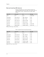
Page 42: ...Yellow with traffic 100Mbps half duplex PB100 Solid yellow Green with traffic 100Mbps full duplex PB100 Solid green Yellow with traffic 1000Mbps half duplex PB100 PB200 Solid green Green with traffic 1000Mbps full duplex PB100 PB200 Table 4 8 RJ45 Copper interface LEDs Speed LED Activity LED Link Blade type Not lit Not lit No link PB100 Blinking yellow Yellow with traffic 10Mbps half duplex PB100 ...

Page 43: ... LED Activity LED Link Blade type Not lit Not lit No link PB200 Not supported Not supported 10Mbps half duplex PB200 Not supported Not supported 10Mbps full duplex PB200 Not supported Not supported 100Mbps half duplex PB200 Not supported Not supported 100Mbps full duplex PB200 Not supported Not supported 1000Mbps half duplex PB200 Solid yellow Green with traffic 1000Mbps full duplex PB200 Not supp...

Page 44: ...Chapter 4 4 10 ...

Page 45: ...5 VIPRION Platform Maintenance About maintaining the VIPRION platform Changing blades Changing the fan tray Changing a power supply Removing and replacing the LCD component ...

Page 46: ......

Page 47: ... use To add a new blade you first remove the blank from the corresponding slot and then insert the correct blade Note We recommend that you install blades into the chassis starting at the top slot and then into each subsequent slot moving down WARNING This product is sensitive to electrostatic discharge ESD We recommend that when you install or maintain the unit you use proper ESD grounding proced...

Page 48: ...osition Figure 5 2 A compression screw in the red unlocked position 3 Grasp the two eject levers on the front of the blank and pull towards you as shown in Figure 5 3 You can now remove the blank from the slot and add the new blade Figure 5 3 Extending an eject lever ...

Page 49: ...ooves on the interior of the slot as shown in Figure 5 4 Figure 5 4 Aligning the blade in the slot Important Verify that the blade is aligned with these grooves otherwise the blade does not seat correctly in the platform 3 Slide the blade in until it is fully seated in the slot 4 When the eject levers engage the chassis press the eject levers on the blade towards the center of the blade until they...

Page 50: ...green locked position as shown in Figure 5 1 on page 5 2 Note The locking indicator on the compression screws turns green before the screws are completely secured to the platform however we highly recommend that you continue turning the screws until they are firmly secured 6 Repeat this process with each blade until all blades are secured in the platform ...

Page 51: ... 30 seconds WARNING Operating the platform for longer than 30 seconds without a fan tray can cause permanent damage to the blades To replace the fan tray 1 Standing in front of the platform locate the fan tray handle The fan tray handle is located in the middle of the fan tray which is located on the left side of the chassis 2 Extend the fan tray handle by pressing the top portion of the handle in...

Page 52: ...em is unaffected by the loss of a single supply For details about power requirements see AC power requirements on page 9 2 Adding a power supply The platform can contain a total of four power supplies By default the platform includes four power supplies one installed in each power supply bay Note You do not need special tools to replace a power supply To add a power supply 1 Using the indentations...

Page 53: ... operating In this situation you must add the power supply to another power supply bay and then remove the old power supply To replace a power supply 1 Using the indentations on either side of the LCD component pull the LCD component off the platform With the LCD component removed you can see the power supplies and the available power supply bays 2 Unscrew the fastener located in the middle of the...

Page 54: ... the LCD component 1 To remove the original LCD component grasp the LCD component on either side using the indentations provided Note Failure to use the indentations could result in pinched fingers 2 Pick up the replacement LCD component using the indentations provided 3 Align the guide pins on the panel to the corresponding holes in the chassis as shown in Figure 5 6 Figure 5 6 Replacing the LCD ...

Page 55: ...nance Platform Guide VIPRION 5 9 4 Press the LCD component onto the corresponding connections at the front of the platform until it clicks into place as shown in Figure 5 7 Figure 5 7 Pressing the LCD component into position ...

Page 56: ...Chapter 5 5 10 ...

Page 57: ...6 Guidelines for DC Power in the VIPRION Platform About the DC power supply option for the VIPRION platform VIPRION DC power supply specifications ...

Page 58: ......

Page 59: ...N Platform to install a DC powered VIPRION platform in a rack The chassis should be installed in a rack and have at least one blade installed This power supply does not have an on off switch You can control the power from the rack switch or the DC power source Important You must use copper wire for the ground wire and all lead wires Important The VIPRION platform must be installed in a restricted ...

Page 60: ... is installed in a rack you can ground the platform Each blade has a metal plate that is screwed to the electronics in multiple places to the ground plane of the board The front plate of the blade is also screwed to this plate when you tighten the screw lock assemblies to the chassis The entire system is directly connected to the metal chassis and the ground connection is also directly connected t...

Page 61: ...e the Molex crimping tool to crimp the ground wire to the two ring grounding terminal lug F5 Networks recommends using a 2 AWG copper wire for grounding 3 Attach the two ring ground terminal lug Figure 6 1 to the ground terminal 4 Install the 5 16 18 Keps nuts on the ground terminal lugs Use 16 to 18 inch pounds 1 8 to 2 0 newton metres of torque on these nuts 5 Connect the ground wire to a common...

Page 62: ...8 2 There are two groups of terminals on the back of the chassis When you view the chassis from the rear there is one on the left side and one on the right side Each terminal group contains the leads for two power supplies Use the group of leads on the right rear of the chassis labeled PWR 2 and PWR 1 for power supplies 2 and 1 Use the group of leads on the left rear of the chassis labeled PWR 4 a...

Page 63: ...ach wire where you connect the wire to the terminal block plug 3 Connect the positive DC wire to the RTN terminal on the terminal block plug You should strip at least 0 50 in 12 7 mm of insulation off of each wire where you connect the wire to the terminal block plug 4 Wire each supply in this manner until you have wired each terminal block plug for two power supplies 5 Plug each terminal block pl...

Page 64: ...o blade slots with no redundancy Table 6 2 shows some of the possible blade and power supply redundancy configurations Item Specification Power supply 1200W maximum output Rated input voltage 36 to 72 VDC Input current 10 to 40A maximum per supply Table 6 1 The VIPRION DC power supply specification Blade quantity No redundancy 1 1 redundancy 1 600W 1 1200W available 2 1200W available 2 1200W 1 120...

Page 65: ...ion of the VIPRION platform WARNING The intra building interfaces of this platform including Ethernet are suitable for connection to intra building or unexposed wiring or cabling only with shielded and grounded cables at both ends The intra building ports of the equipment must not be metallically connected to interfaces that connect to the outside plant OSP or its wiring Blade quantity and type Ty...

Page 66: ...Chapter 6 6 8 ...

Page 67: ...7 Platform Airflow Platform airflow information ...

Page 68: ......

Page 69: ...o understand the unit s airflow direction so that you can ensure proper cooling Airflow for VIPRION platforms The VIPRION platforms employ a negative pressure fan system which draws cold air in from the right and front sides of the chassis and exhausts hot air out the left and back sides of the chassis Table 7 1 Airflow in VIPRION platform ...

Page 70: ...Chapter 7 7 2 ...

Page 71: ...8 Environmental Guidelines for the VIPRION Platform Environmental requirements ...

Page 72: ......

Page 73: ...k according to the manufacturer s instructions and check the rack for stability before placing equipment in it Build and position the rack so that once you install the VIPRION platform the power supply and the vents on both the front and back of the unit remain unobstructed The VIPRION platform must have adequate ventilation around the unit at all times Do not allow the air temperature in the room...

Page 74: ...eed is used for each individual power supply Guidelines for DC powered equipment A DC powered installation must meet the following requirements Install the unit using a 50 Amp external branch circuit protection device per power feed For permanently connected equipment incorporate a readily accessible disconnect in the fixed wiring Use only copper conductors Normally one power feed is used for each...

Page 75: ...rm Specifications General specifications for system features AC power requirements PB100 blade specifications PB200 blade specifications J100 chassis specifications Acoustic airflow and altitude specifications ...

Page 76: ......

Page 77: ...al contributed software SNMP gets and traps iControl API using CORBA SOAP XML Dynamic Content Support ASP active server pages VB visual basic script ActiveX JAVA VRML CGI Cool Talk Net Meeting Real Audio Real Video Netshow Quick Time PointCast any HTTP encapsulated data Device Redundancy Watchdog timer fail safe cable primary secondary Web Server Application Compatibility Any IP based web or appli...

Page 78: ...upports one to four AC power supplies The power supplies are auto ranging 90VAC to 240VAC input Each slot is provisioned to draw up to 600W therefore one power supply with low line input can support two blades with no redundancy or the same supply with high line input can support up to three blades Table 9 2 shows some of the possible blade and power supply redundancy configurations Table 9 2 AC p...

Page 79: ... power draw high line input Blade quantity and type Typical system power draw Maximum system power draw Number of power supplies installed 1 x PB100 650W 875W 2 2 x PB100 950W 1250W 2 3 x PB100 1300W 1625W 4 4 x PB100 1600W 2000W 4 1 x PB200 675W 900W 2 2 x PB200 1000W 1300W 2 3 x PB200 1375W 1700W 4 4 x PB200 1700W 2100W 4 Blade quantity and type Typical system power draw Maximum system power dra...

Page 80: ...processors Network Interfaces 1x10 100 1000 Ethernet Management port 8x10 100 1000 Copper ports 12x1000Base X SFP Fiber Copper ports 1000BASE SX 850nm LC Connector 4 modules included 1000BASE LX 1310nm LC Connector optional 1000BASE T Copper SFP RJ45 Connector optional 10BaseT 100BaseT 1000BaseT Copper SFP RJ45 Connector optional 2x10 Gigabit XFP ports 10GBASE SR 850nm LC Connector optional Hard D...

Page 81: ... AMD Opteron processors Network Interfaces 1x10 100 1000Mbps Ethernet management port 4x1000Mbps Ethernet copper ports 8x1000Mbps 10Gps Ethernet SFP fiber ports 10GBASE SR 850nm LC Connector two modules included 10GBASE LR LW 1310nm LC Connector optional 1000BASE SX 850nm LC Connector optional 1000BASE LX 1310nm LC Connector optional Hard Drive Capacity 160 Gigabyte ATA hard drive 8 Gigabyte Compa...

Page 82: ...plies 2 blanks 105 lbs 47 6 kg Empty chassis 3 blank cards 0 power supplies 0 blades 1 fan tray 1 System ID card 69 lbs 31 3 kg Power supply 4 5 lbs 2 0 kg PB100 blade 14 5 lbs 6 58 kg PB200 blade 14 5 lbs 6 58 kg Blank line card 2 lbs 0 9 kg Fan tray 8 5 lbs 3 9 kg System ID card 0 5 lbs 0 2 kg Processor See blade specifications Hard Drive Capacity See blade specifications RAM See blade specifica...

Page 83: ...tude for the VIPRION platform Specification type Detail Units Chassis with line card Acoustica a Fans at 75 All measurements taken at 0 6 meter A weighting Front face db 72 Left face db 77 Right face db 75 Rear face db 67 Altitudeb b 60 meters 197 feet below sea level to 1800 meters 5905 feet above sea level Operational Feet 5905 Non operational Feet 40000 Airflow Entire chassis cfm 650 Table 9 8 ...

Page 84: ...Chapter 9 9 8 ...

Page 85: ...A Platform Specific Hazardous Substance Levels for China VIPRION chassis VIPRION blades ...

Page 86: ......

Page 87: ...ific Hazardous Substance Levels for China Platform Guide VIPRION A 1 VIPRION chassis This table lists hazardous substances controlled by China and shows how the F5 Networks VIPRION platform conforms to the standards ...

Page 88: ...Appendix A A 2 VIPRION blades This table lists hazardous substances controlled by China and shows how the F5 Networks VIPRION PB100 and PB200 blades conform to the standards ...

Page 89: ...Glossary ...

Page 90: ......

Page 91: ... the blade in the primary slot is removed or becomes unavailable another slot in the cluster automatically becomes the primary slot and the cluster IP address becomes associated with the new primary slot You use this IP address to manage the cluster compression screw A compression screw ensures that a given VIPRION component is securely attached to the chassis Each screw indicates by color whether...

Page 92: ... tray that you can replace without affecting system performance LCD LCD display stands for liquid crystal display An LCD panel is available on the front of the platform You can use the LCD and its associated controls to configure the management port on the unit and view basic statistics LCD component The LCD component is the hardware component that contains the LCD and the LEDs that display power ...

Page 93: ...Index ...

Page 94: ......

Page 95: ...nt 3 6 mixed 2 2 common bonding network 6 2 components provided with VIPRION platform 1 4 compression screws securing 5 4 unsecuring 5 1 Configuration utility about online help 1 6 about the Welcome screen 1 6 cooling system for platform 7 1 copper module types 9 4 D DC power supply and VIPRION platform 6 1 DC powered equipment and environmental guidelines 8 2 and NEBS information 6 7 and specific...

Page 96: ...vigating 3 3 LCD panel 3 1 configuring 3 2 for Options menu 3 3 for Screens menu 3 5 for System menu 3 4 LED behavior 4 1 for blade alarms 4 1 for chassis alarms 4 1 for chassis status 4 1 for network interfaces 4 8 for power supply 4 1 LED indicators when green 4 4 when yellow 4 4 liquid crystal display See LCD M maintainence and fan tray 5 5 maintenance and blades 5 1 and LCD component 5 8 and p...

Page 97: ...tic 9 7 airflow 9 7 altitude 9 7 J100 9 6 PB100 9 4 PB200 9 5 platform 9 1 specifications hardware for China material content A 1 A 2 standard operating state See LED indicators status LED 4 1 switches 1 5 system airflow See airflow system installation 2 1 System menu 3 1 3 4 system power consumption 6 7 system power consumption AC 9 3 T technical documentation finding 1 6 technical support web si...

Reviews: