Front Panel LEDs
ARX-500 Hardware Installation Guide
4 - 5
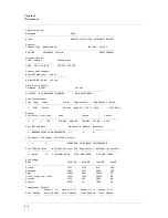
NVR:
NVR
Battery
ECC
State
NVR
Size
(MB)
‐‐‐‐‐‐‐‐‐‐‐ ‐‐‐‐‐‐‐‐‐‐‐‐‐‐‐‐‐‐‐‐‐‐ ‐‐‐‐‐‐‐‐‐‐‐‐‐
Good
No
Error
128
Front Panel LEDs
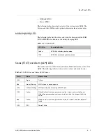
This section describes the ARX-500 LEDs located on the far right side of
the control panel.
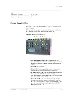
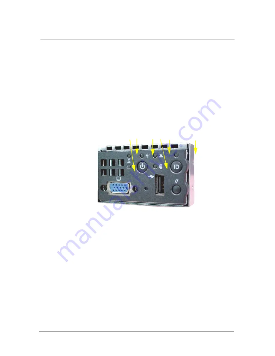
LEDs on the front control panel include the LEDs shown in the following
figure, matched with the list of LEDs following the diagram.
Figure 4.1
ARX-500 Front Panel LEDs
a)
OOB management (NIC2) LED
.
Continuous green light
indicates a link between the system and the management network
to which it is connected. Blinking green light indicates network
activity.
b)
NIC1 LED
.
Not supported.
c)
Power LED
.
Continuous green light indicates the system has
power applied to it. No light indicates the power is off.
d)
Hard drive activity LED
.
Random blinking green light indicates
hard-disk activity (IDE). The hard disk is used by
system-management processes such as the CLI and GUI. No light
indicates no hard disk drive activity.
e)
System Fault LED
. Solid green indicates normal operation.
Blinking green indicates degraded performance. Solid yellow
indicates a critical or non-recoverable condition. Blinking yellow
indicates a non-critical condition. No light indicates POST is
running or the system is off.
a b
c
d
e
f
Summary of Contents for ARX-500
Page 1: ...ARX 500 Hardware Installation Guide 810 0039 00 ...
Page 2: ......
Page 7: ...Table of Contents ...
Page 8: ......
Page 10: ...Table of Contents x ...
Page 11: ......
Page 12: ...Table of Contents xii ...
Page 14: ......
Page 22: ......
Page 32: ......
Page 50: ...Chapter 3 Connecting the Switch to the Network 3 20 ...
Page 51: ...4 Maintenance Powering Down the ARX 500 POST Diagnostics Front Panel LEDs Rear Panel LEDs ...
Page 52: ......
Page 59: ...Index ...
Page 60: ......
Page 62: ...Index Index 4 ...


