


www.ezurio.com
DSH_BT024-00200_1v4 © Ezurio Ltd 2006
15
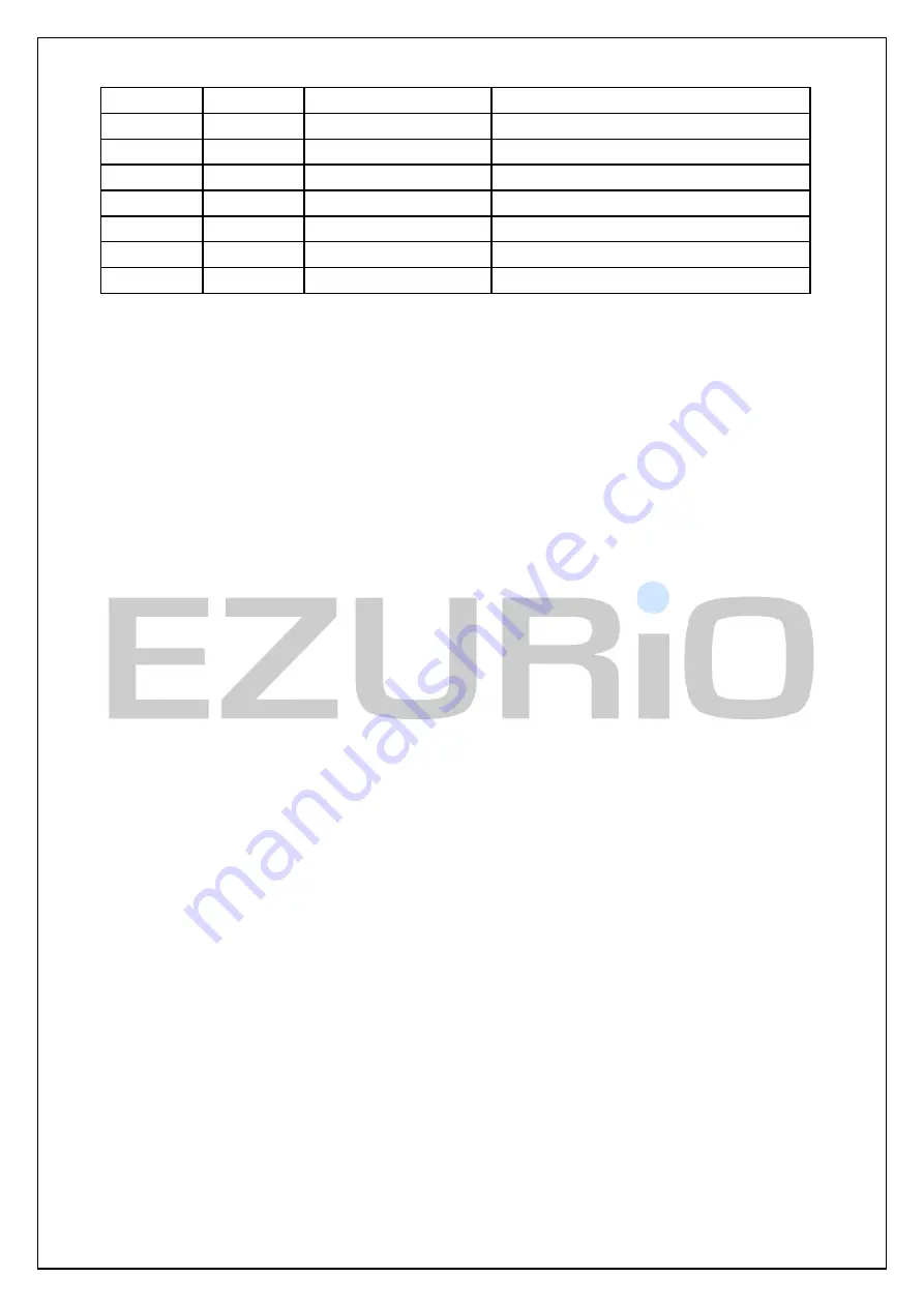
Pin
Direction
Connector Pin Label
Function
27
IN/OUT
GPIO_3/UART_DTR
General Purpose I/O (or DTR functionality)
36
IN/OUT
GPIO_4/LED1
General Purpose I/O (LED1)
35
IN/OUT
GPIO_5/LED2
General Purpose I/O (LED2)
6
IN/OUT
GPIO_6
General Purpose I/O
7
IN/OUT
GPIO_7
General Purpose I/O
38
IN/OUT
GPIO_8
General Purpose I/O
34
IN/OUT
GPIO_9/PCM_SLVCLK
General Purpose I/O (PCM SLAVE CLK)
Notes:
1.
UART_DSR is used by the module to sense that the host is connected, and is intricately linked with
connections. For outgoing calls, if this line is not asserted then an error is indicated. Similarly for AT+BTP and
AT+BTG.
While in a call, for appropriate modes, a de-assertion means fall into command state. If the de-assertion exists
for longer than the period specified in S Register 519 then the connection is dropped as if an ATH command was
received.
2.
UART_RI, is normally de-asserted. When an incoming connection is detected it will be asserted, until the
connection is either answered or rejected using ATA and ATH respectively. See S Registers 552 & 553 for more
details
3.
UART_DCD will be de-asserted when the device is in the unconnected state. Asserted when a connection
is active. See S Registers 552 and 553 for more details.
4.
GPIO_3 is either used as GPIO or driven as UART_DTR. When the unit is configured in pure host mode,
this pin is forced into UART_DTR and is asserted when there is a
Bluetooth
connection.
5.
GPIO_9 can be used to generate a PCM clock when both connected modules are in slave mode. Contact
Ezurio for more information.
The GPIO Pins are available for general purpose use.
9.2
Modem signalling over
Bluetooth
The RFCOMM protocol used in
Bluetooth
for implementing the serial port profile allows for the exchange of four
modem signals. This information is contained in a special transparent message which contains bits identified as
RTR, RTC, DV and IC which depending on the type of serial device being emulated maps to DTR or DSR, RTS,
DCD and RI respectively. In addition, this message also includes the ability to convey a BREAK input from one
end to the other.
To allow for the greatest flexibility and variability in how the modem control signals are used in the real world, S
Registers 551, 552 and 553 have been provided which allow for any of RTR, RTC, DV and IC to be mapped to any
modem control/status line.
BREAK signal on RX line
If the host sends a break signal of duration greater than 100ms, then the module is configured to treat
that as a signal to perform a hardware reset.
This being the case it is not possible to convey a BREAK over
Bluetooth
to the peer device.
A continuous low on the RX line will be treated by the module as a reset (BREAK). Therefore the host
should keep RX high while idling.
Reset
The module can be reset by the host without the need of any I/O using a BREAK signal. The module has
been configured to reset when the RX line detects a break condition for durations greater than 100
milliseconds.
The Reset line has a fixed pull up resistor of 10k Ohm