background image

The vibrator grate

 / safety cover is used to both protect the operator and to assist in the grading of the 

material passing into the pumping hopper. The grate will prevent items larger in size than the rotor / stator 

can process. 

The vibrator grate must be in the lowered position during operation.


The vibrator grate hinges upwards and swings past vertical to allow for unobstructed access to the hopper. 

OPERATIONS

Shown with optional vibrat

or

 motor.

If access is required into the hopper, then turn off the engine before lifting the grate. Pump can be

disassembled by removing the clamping nuts facilitating easier clean up.

The 38 Special Pump is supplied with an adjustable stator. The sleeve can be tightened to bring

working pressure back to normal range as the stator wears. This should be done evenly along the

length and in small increments. Over-tightening the stator will cause premature wear and heat up

material.

Always check hoses and cords for wear.

The unit runs at high pressures and temperatures. Use caution when moving or touching parts of

the unit.

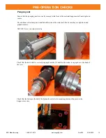
Check the condition of the Universal joint seal tube. Look for signs of wear or cuts on the tube.

Check that all fasteners are all secure.

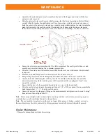
Grease drive shaft seal daily with water resistant, corrosion inhibited grease via the grease fitting /

Zerk in the motor flange.

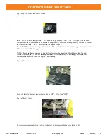
For starting the pump, ensure that the throttle is at maximum and direction control is set to

“FWD”.

Do not let hopper run dry while pump is running.

To stop machine Move the Pump Control Panel switch to the center position.

If a hose becomes plugged while pumping, stop the machine, then reverse the driveshaft direction

on pump to relieve line pressure using the Pump Control Panel switch set to “REV”.

Never point a hose towards personnel when pump is working.

When cleaning the pump, do not remove the safety grate while pump is running. Wash out hopper

with water and let it run out of the hose. When the hopper is clean, run foam balls through hose

with clean water. Then wipe down with a damp rag.

Hopper draining can be assisted by the removal of the drain plug from the lower section of the

hopper.

General notes for operation

EZG Manufacturing                    1-800-417-9272

                    www.ezgmfg.com

Rev000           5/24/2022            20

Summary of Contents for 38 Special Pump

Page 1: ...id Steer Serial Number __________________ Before using this equipment study and understand entire Owner s Manual EZG Manufacturing 405 Watertown Road Waterford Ohio 45786 740 749 3512 or 1 800 417 9272 Fax 740 962 2037 www ezgmfg com 38 Special Pump EZG Manufacturing 1 800 417 9272 ...

Page 2: ...utions 5 Proposition65Warning 7 Controls Switches 8 Towing 10 Pre Operation Checks 11 Operations 20 Maintenance 21 Rotor and Stator Pump Adjustments 25 Warranty 27 Registration 28 Rotor Stator Replacement 26 EZG Manufacturing 1 800 417 9272 www ezgmfg com Rev000 5 24 2022 2 TABLE OF CONTENTS ...

Page 3: ...pped with a 3 inch pipe wing nut expanding plug to facilitate quick and efficient cleanup The well designed operator control panel includes pressure gauge a control panel for speed adjustment and forward and reverse operations a switch for the optional vibrator motor available option on HP38SM and HP38 only and a tiny tach The E Stop is located on the face of the electrical box inside the enclosur...

Page 4: ...ow to safely operate the machine and become aware of hazards It also contains important information regarding set up operation maintenance and repair procedures It is the responsibility of the equipment owner operator to make sure anyone who operates this machine understands all safety warnings If you do not understand any items in this manual please contact the dealer where this product was purch...

Page 5: ...ith the safety grate guards or safety devices removed or open Do not alter any safety guards Be sure any clothing you wear does not have strings fringes or other external tightening means that could be caught in moving parts Keep all body parts clothing jewelry and solid objects away from all moving parts Never perform any work on the machine while it is running Before working on or cleaning the u...

Page 6: ...fore connecting to the HP38 Safety chains must be used with HP38 when unit is in tow Insure tow vehicle and hitch have a rated GCWR GTW and tongue weight capacity to handle HP38 Alway chock wheels of HP38 when not coupled to a tow vehicle Model Empty Weight Tongue Weight HP38SS Model Tire Size Tire Pressure HP38 ST225 75R15 65 psi 245 kPa SAFETY PRECAUTIONS Model Empty Weight Tongue Weight HP38SM ...

Page 7: ...se chemicals ALWAYS work in a well ventilated area and work with approved safety equipment such as dust masks that are specially designed to filter out microscopic particles SAFETY PRECAUTIONS Hydraulic System The hydraulic system is under pressure and oil may be hot Always allow the machine to cool completely before performing service Always relieve pressure in the hydraulic system before performi...

Page 8: ...ration and can be adjusted during operation System pressure gauge reading pressure of the motor system during rotation The picture below shows the vibrator motor option The vibrator switch is located on the fuel tank side of the engine enclosure and operates the vibrator motor mounted on the hinged grate on top of the pumping hopper This is used to assist grading the material through the grate Do ...

Page 9: ...ngine starter When released it will disengage NOTE The engine has power generation abilities to cover the operation of both the cooling fan and vibrator while running When not running the battery will drain rapidly It is strongly advised that all switches be turned OFF when the engine is not running Engine Choke lever Move the lever to the right to operate the choke ON left to turn OFF Engine Thro...

Page 10: ...olted to the tongue assembly and must be pinned closed when coupled to the tow vehicle The hitch can be raised and lowered to suit tow ball height using the different hole positions provide in the tongue assembly It is suggested that the unit be placed as close as is practicably possible to the discharge location so that excessive pumping distances can be avoided helping to minimize the burden on ...

Page 11: ... at all times to ensure that the motor and hydraulic fluid are correctly cooled Pay attention to the engine exhaust flow toward the right side of the engine enclosure as it will be hot and contain exhaust fumes Prior to operation ALL fluid levels should be checked and be in good order PRE OPERATION CHECKS EZG Manufacturing 1 800 417 9272 www ezgmfg com Rev000 5 24 2022 11 ...

Page 12: ...ling is carried out through the filler cap Hydraulic fluid Hydraulic oil level is checked though the sight tube from the outside of the machine Filling access is on top of the enclosure located to the rear of the left side DAILY PRE OPERATION CHECKS EZG Manufacturing 1 800 417 9272 www ezgmfg com Rev000 5 24 2022 12 ...

Page 13: ...ually inspecting the tank via the filler opening Warning Do not drain fuel system completely of fuel Danger Do not fill while the engine is running Danger Do not fill while the engine is hot DAILY PRE OPERATION CHECKS View shown with 8 gallon tank 16 gallon tank available EZG Manufacturing 1 800 417 9272 www ezgmfg com Rev000 5 24 2022 13 ...

Page 14: ...e of hydraulic oil in the system correct operation of the fan is critical Ensure that the vent and the fan are clear of all obstructions The cooling fan exhaust is diverted through the top of the enclosure via a heat shroud DAILY PRE OPERATION CHECKS Keep this area clear of dirt and debris Heat Shield EZG Manufacturing 1 800 417 9272 www ezgmfg com Rev000 5 24 2022 14 ...

Page 15: ...ake sure they are tightened and pinned securely NOTICE Never run rotor stator dry Check that the drive shaft is correctly engaged into the UJ and that the socket is engaged over the head of the rotor Check that the fasteners that hold the hydraulic motor to its mounting plate and the plate to the hopper are secure PRE OPERATION CHECKS EZG Manufacturing 1 800 417 9272 www ezgmfg com Rev000 5 24 202...

Page 16: ...ubber bumper feet Rubber Poly bumper shown Ensure that ALL fasteners are present in good condition and tightened securely prior to any operation DAILY PRE OPERATION CHECKS Shown with optional vibrator motor EZG Manufacturing 1 800 417 9272 www ezgmfg com Rev000 5 24 2022 16 ...

Page 17: ...tator housing clamp is necessary Stator Housing Clamp Adjustment Step 1 Remove stator cover Step 2 With the engine running as described in the previous section loosen the bolts indicated by the number 3 Start at one end and tighten the adjusting bolts as indicated by the number 1 in the picture below Tighten stator housing bolts evenly to adjust the pressure on the pressure test rig 1 4 to 1 2 tur...

Page 18: ...s Step 2 Turn off engine Step 3 Open ball valve on test rig to drain Remove expansion plug to drain hopper Step 4 Remove test rig from outlet Step 5 Replace expansion plug in hopper DAILY PRE OPERATION CHECKS EZG Manufacturing 1 800 417 9272 www ezgmfg com Rev000 5 24 2022 18 ...

Page 19: ...he engine using the ignition starter key Once running progressively open the choke lever by sliding to the left until the engine runs without hesitation Let the engine warm up for a few minutes For troubleshooting the engine start up refer to the engine user manual supplied Shut Down When shutting down move the switch on the pump control panel to the middle off position then slow the engine to idl...

Page 20: ...Use caution when moving or touching parts of the unit Check the condition of the Universal joint seal tube Look for signs of wear or cuts on the tube Check that all fasteners are all secure Grease drive shaft seal daily with water resistant corrosion inhibited grease via the grease fitting Zerk in the motor flange For starting the pump ensure that the throttle is at maximum and direction control i...

Page 21: ... hopper When cleaning also pay attention to the grease seal around the drive Universal joint fixed to the drive flange at the rear of the machine Seal Greasing Ensure that the seal between the drive coupling and the motor is greased each day or after each clean down with a water resistant corrosion inhibiting extreme pressure grease Grease until a small amount of grease can be seen oozing from aro...

Page 22: ...be in the opposite direction towards the driveshaft until the set screw is exposed in the UJ that secures it to the motor shaft Loosen the set screw Remove the universal Joint Remove the four fixing nuts from the flange plate and withdraw the motor assembly from the hopper rear Remove the rubber seal from the counterbore in the plate Thoroughly clean the seal area and the flange Ensure that the ol...

Page 23: ...resh grease inside the UJ through the driveshaft hole until it is about 2 from the end Assemble the driveshaft complete with key into the UJ until the collar touches the end of the universal joint during which time the grease will be pushed into the coupling and ooze from around the seal tube Ensure that the key is fully assembled then lock the set screw to the keyed shaft Slide the seal tube back...

Page 24: ...quired especially for climates likely to freeze Freezing is mainly a problem for items containing water The engine and hydraulics do not need to be winterized however it is recommended that the fuel in the fuel tank be stabilized for extended periods of storage Follow the engine manufacturer s instructions for extended storage and winterization Battery The battery should be placed on a battery mai...

Page 25: ...astomer wears within a very short time Even if dry running lasts only a few seconds with new parts the effect resembles that of a wheel spin on a car tire dramatically affecting length of service The use of simple dish soap or specific water based lubricants mixed with water whilst hose cleaning or pump priming can dramatically reduce the negative effects of dry running and help prolong the natura...

Page 26: ...g to see if it has rotated If any rotation has occurred then turn off the engine If the stator housing adjustment flange is resting against the guide bolt then rotate the flange away from bolt The guide bolt should remain approximately in the center of the adjustment gap x Evenly tighten the nuts on the threaded rods to apply more pressure against the stator housing Once the stator housing no long...

Page 27: ... abuse failure to perform normal maintenance on the product use of non manufacturer parts or failure to follow documented service instructions alterations or modifications made to the product without the written approval of EZG 8 EZG will pay shop labor on warranty items at the EZG Shop Labor Rate in existence on the date of the warranty claim EZG technician will determine the time allowed to comp...

Page 28: ...BBBBBBBBBBBBBBBBBBBBBBBBBBBBBBBBBBBBBBBBBBBBBBBB WHAT INFLUENCED YOU TO BUY QUALITY PRICE EASY TO USE OTHER WHO IS YOUR SALES REPRESENTATIVE BBBBBBBBBBBBBBBBBBBBBBBBBBBBBBBBBBB ARE YOU SATISFIED WITH THE CUSTOMER SERVICE YOU RECEIVED YES NO Explain BBBBBBBBBBBBBBBBBBBBBBBBBBBBBBBBBBBBBBBBBBBBBBBBBBBBBBBBBBBBBB BBBBBBBBBBBBBBBBBBBBBBBBBBBBBBBBBBBBBBBBBBBBBBBBBBBBBBBBBBBBBBBBBBBB WHAT OTHER EZ 0 18 ...

Reviews: