background image


XTP SR HDMI Scaling Receiver • XTP System Configuration Software

44

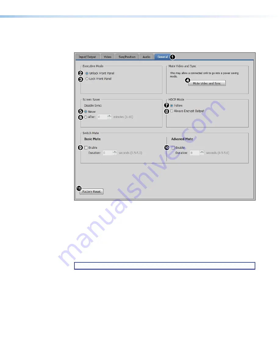
General tab

Click the 

General

 tab (see figure 35, 

1

) to open the 

General

 screen. This screen contains 

executive mode and video and sync settings.

Figure 35. 

General Tab

Executive Mode panel

The 

Executive Mode

 panel on the 

General

 screen is used to enable or disable front panel 

lockout mode (executive mode).

2


Unlock front panel

 — Click the 

Unlock Front Panel

 radio button (default) to disable 

executive mode and allow full use of the receiver front panel.

3


Lock front panel

 — Click the 

Lock Front Panel

 radio button to enable executive 

mode and lock the front panel.

NOTE:

  In executive mode, access to the OSD menu is disabled.

Mute Video and Sync panel

The 

Mute Video and Sync

 panel on the 

General

 screen is used to mute or unmute 

output video and sync.

4


Mute video and sync

 — Click the 

Mute Video and Sync

 button to mute the active 

video and disable sync on the output.

Summary of Contents for XTP SR HDMI

Page 1: ...User Guide XTP SR HDMI XTP Systems XTP HDMI Scaling Receiver 68 2007 01 Rev H 01 19...

Page 2: ...encia 68 290 01 en el sitio Web de Extron www extron com Instructions de s curit Fran ais AVERTISSEMENT Ce pictogramme lorsqu il est utilis sur le produit signale l utilisateur la pr sence l int rieur...

Page 3: ...Lane IP Intercom IP Link Key Minder LinkLicense LockIt MediaLink MediaPort NetPA PlenumVault PoleVault PowerCage PURE3 Quantum Show Me SoundField SpeedMount SpeedSwitch StudioStation System INTEGRATOR...

Page 4: ...tion manual may cause harmful interference to radio communications Operation of this equipment in a residential area is likely to cause interference This interference must be corrected at the expense...

Page 5: ...f computer or device responses mentioned in this guide the character 0 is used for the number zero and O represents the capital letter o Computer responses and directory paths that do not have variabl...

Page 6: ...utput Configuration Submenu 19 Advanced Configuration Submenu 21 Front Panel Lockout Mode Executive Mode 22 Reset Mode 22 SIS Configuration and Control 23 Host Device Connection 23 SIS Overview 23 Hos...

Page 7: ...bidirectional RS 232 and IR and Ethernet signals over a single twisted pair cable It is HDCP compliant and supports 1080p 60 Deep Color 1920x1200 signals and embedded HD lossless audio formats It work...

Page 8: ...le 330 HDMI Cable Projector Extron XTP T USW 103 XTP Transmitter Extron XTP SR HDMI XTP Scaling Receiver Ethernet Figure 1 Typical XTP SR HDMI Point to Point Application System Compatibility The XTP S...

Page 9: ...to reduce the amount of independent network drops required within a system Remote power capability Allows the XTP SR HDMI to be powered by an XTP CrossPoint Matrix Switcher or XTP Power Injectors to s...

Page 10: ...e 5 E Analog audio output connector see page 6 F S PDIF audio output connector see page 6 G Relay connectors see page 6 H Remote RS 232 connector see page 6 I Power connector and LED see page 6 Figure...

Page 11: ...XTP port To pass bidirectional serial signals between XTP compatible devices connect a control device to the 5 pole captive screw connector see figure 2 C on the previous page The port includes only...

Page 12: ...female orange RCA connector see figure 2 F on page 4 for digital S PDIF audio output see Audio Output Overview on page 15 for supported audio formats on the S PDIF output The type of audio present on...

Page 13: ...the LockIt to be placed over it The screw does not have to be removed 3 Place the LockIt on the screw and against the HDMI connector 3 and then tighten the screw to secure the bracket 4 Loosely place...

Page 14: ...n 4 Blue 5 White blue 6 Green 7 White brown 8 Brown Figure 5 Twisted Pair Cable Termination Supported cables The XTP SR HDMI is compatible with shielded twisted pair F UTP SF UTP and S FTP and unshiel...

Page 15: ...id conductor STP cable with a minimum bandwidth of 400 MHz Terminate cables with shielded connectors to the TIA EIA T568B standard see figure 5 on the previous page Limit the use of more than two pass...

Page 16: ...6 below for wiring considerations Tx Rx Pins Rx Tx RS 232 IR Rx Tx Tx Rx Rx Tx IR Device RS 232 Device G G G Figure 6 Wiring the RS 232 and IR Over XTP Connector ATTENTION The length of the exposed w...

Page 17: ...wiring considerations or remotely through the XTP connector with a power injector or a matrix switcher Local power SECTION A A A A Power Supply Output Cord 2 Pole Captive Screw Connector Ridges Smooth...

Page 18: ...ical Code part 1 section 16 The power supply shall not be permanently fixed to a building structure or similar structure Sauf mention contraire les adaptateurs AC DC ne sont pas appropri s pour une ut...

Page 19: ...Tx RS 232 IR Rx Tx L R LOOP THRU RESET AUDIO OFF ON AUDIO XTP T HDMI LAN SIG LINK XTP OUT INPUTS OVER XTP LAN SIG LINK XTP IN POWER 12V HDMI 1A MAX Rx G Tx RS 232 IR Rx Tx L R 1 2 OVER XTP AUDIO OFF...

Page 20: ...he left side of the rear panel B Configuration port If desired connect a host device to the front panel USB mini B port for configuring the scaling receiver C XTP indicators Signal LED indicator Light...

Page 21: ...n continue to be controlled through SIS commands or from an XTP matrix switcher Audio Output Overview By default an XTP transmitter or matrix switcher prioritizes embedded digital audio over analog au...

Page 22: ...submenus and their respective submenu items Submenus Submenu Items Image Reset Image reset Picture Controls Horizontal vertical position Horizontal vertical size Brightness contrast Detail User Prese...

Page 23: ...position of the image Rotate the Vertical Adjustment knob to adjust the vertical V position of the image The default value is 32 768 Image size Rotate the Horizontal Adjustment knob to adjust the hor...

Page 24: ...n another input allowing them to also be used as aspect ratio or discrete size and center shortcuts There are 8 user preset slots available Figure 12 User Presets Submenu User presets save the followi...

Page 25: ...e Displays the active horizontal H pixels and vertical V lines of the input signal These are not configurable Output Configuration Submenu The Output Configuration submenu is used to configure of the...

Page 26: ...576p X 720p X X X X X X 1080i X X X 1080p X X X X X X X X 2K 2048x1080 X X X X X X X X Default Output format Shows the HDMI output format setting This is not configurable from the OSD menu To configu...

Page 27: ...ern Examples NOTE All test patterns include a single pixel border Blank Rotate the adjustment knobs to turn the blank screen feature on or off When on the screen turns black but the OSD menu is still...

Page 28: ...factory shipped firmware LAN SIG LINK XTP IN POWER 12V HDMI 1 0 A MAX Rx G Tx RS 232 IR Rx Tx L R 1 2 OVER XTP AUDIO OFF ON S PDIF RESET RS 232 Tx Rx G REMOTE RELAYS OUTPUTS AUDIO A Figure 17 Rear Pan...

Page 29: ...re 9 B on page 14 or the rear panel Remote RS 232 connector see figure 2 H on page 4 The protocol for the serial port is as follows 9600 baud no parity 8 data bits 1 stop bit no flow control SIS Overv...

Page 30: ...is configuration E17 Invalid command for signal type E22 Busy Using Command and Response Tables for SIS Commands The command and response tables beginning on page 26 list the commands that the receive...

Page 31: ...table below SIS Variables for Output Resolution and Refresh Rate Combinations where X3 1 47 Resolution 23 98 Hz 24 Hz 25 Hz 29 97 Hz 30 Hz 50 Hz 59 94 Hz 60 Hz 640x480 1 800x600 2 852x480 3 1024x768 4...

Page 32: ...ntrast Set contrast EX CONT ContX Set the contrast to X Increase contrast E CONT ContX Increase the contrast level by one Decrease contrast E CONT ContX Decrease the contrast level by one View contras...

Page 33: ...t E VCTR VctrX Shift the image down by one Decrease vertical shift E VCTR VctrX Shift the image up by one View vertical shift EVCTR VctrX View the vertical position Horizontal size Set horizontal size...

Page 34: ...attern to X1 View test pattern J TstX1 View the current test pattern Video bit depth Set video bit depth EVX1 BITD BitdVX1 Set the video bit depth View video bit depth EVBITD BitdVX1 View the video bi...

Page 35: ...Amt1 Mute the HDMI audio output Unmute all 0Z Amt0 Unmute all audio outputs View mute status Z AmtX1 View the audio mute status Volume Set volume X1 V VolX1 Set output volume to X1 Increase volume lev...

Page 36: ...ect ratio Set aspect ratio to Fill E1ASPR Aspr1 Fill the entire output raster Set aspect ratio to Follow E2ASPR Aspr2 Use the native aspect ratio of the input View aspect ratio setting EASPR AsprX2 Vi...

Page 37: ...px Resets unit to factory default Information Requests View input signal status 0LS FrqX3 View the input signal status View firmware version Q x xx View the firmware version View firmware build Q x xx...

Page 38: ...tware Installation The XTP System Configuration Software is available for download on the Extron website www extron com To download the software from the Extron website locate it on the Download Cente...

Page 39: ...efault the installation creates a directory in the Program Files or Program Files x86 folder Software Product Page Figure 21 XTP System Configuration Software Product Page 1 In the Search field see fi...

Page 40: ...sed to establish communication with an XTP device through a USB connection Ensure the receiver is connected and powered on before attempting to connect to it Figure 22 Connections Screen To connect to...

Page 41: ...ct The Connections screen opens NOTE If the device is already disconnected the Disconnect option is disabled until a device is connected Exit This option disconnects the switcher from the software and...

Page 42: ...tions Select file from computer Uploads a manually selected firmware file saved on the connected computer Check network for updates Checks the connected network for firmware updates If any are found c...

Page 43: ...re This option provides basic information about the XTP System Configuration Software including version number and copyright information Figure 29 About Dialog Box 1 From the Help menu select About th...

Page 44: ...he Global Navigation Bar to open the Device Settings screen Figure 30 Device Settings Screen AV Controls panel The AV Controls panel located on the left is used to perform audio or video mutes NOTE Th...

Page 45: ...nd output configurations as well as relay controls Figure 31 Input Output Tab Input panel The Input panel on the Input Output screen is used to set the aspect ratio 2 Aspect Ratio From the Aspect Rati...

Page 46: ...h From the Video Bit Depth drop down list see figure 31 6 on the previous page set the color bit depth of the output signal 7 Test Pattern From the drop down list below the test pattern preview see fi...

Page 47: ...the slider for the desired setting Click in the desired field to the right of the slider and enter a new value Click the Up and Down arrows to the right of the desired setting 1 Brightness Adjust the...

Page 48: ...portions 1 Click and drag the drag points of the sample image in the Preview box 3 to resize the image within the designated space defined by the black area in figure 33 above 2 Click anywhere inside...

Page 49: ...ute All Click the Mute All button to mute or unmute all audio output When muted the button turns red 3 Volume fader Click and drag the handle of the Volume fader enter a value in the Volume field or c...

Page 50: ...e mode 2 Unlock front panel Click the Unlock Front Panel radio button default to disable executive mode and allow full use of the receiver front panel 3 Lock front panel Click the Lock Front Panel rad...

Page 51: ...age to always encrypt the output regardless of the encryption status of the input signal Switch Mute panel The Switch Mute panel on the General screen is used to enable or disable mutes during switchi...

Page 52: ...e indicator to the left turns green when there is an input signal present 4 Aspect Ratio Displays the aspect ratio 5 Resolution Displays the output resolution and refresh rate 6 Output Format Displays...

Page 53: ...mperature If installed in a closed or multi unit rack assembly the operating ambient temperature of the rack environment may be greater than room ambient temperature Therefore install the XTP SR HDMI...

Page 54: ...b Emirates Dubai This Limited Warranty does not apply if the fault has been caused by misuse improper handling care electrical or mechanical abuse abnormal operating conditions or if modifications wer...

Reviews: