background image

IPI 100 and IPI 200 Series • Operation

3-2

Operation


Front Panel Features and Operation

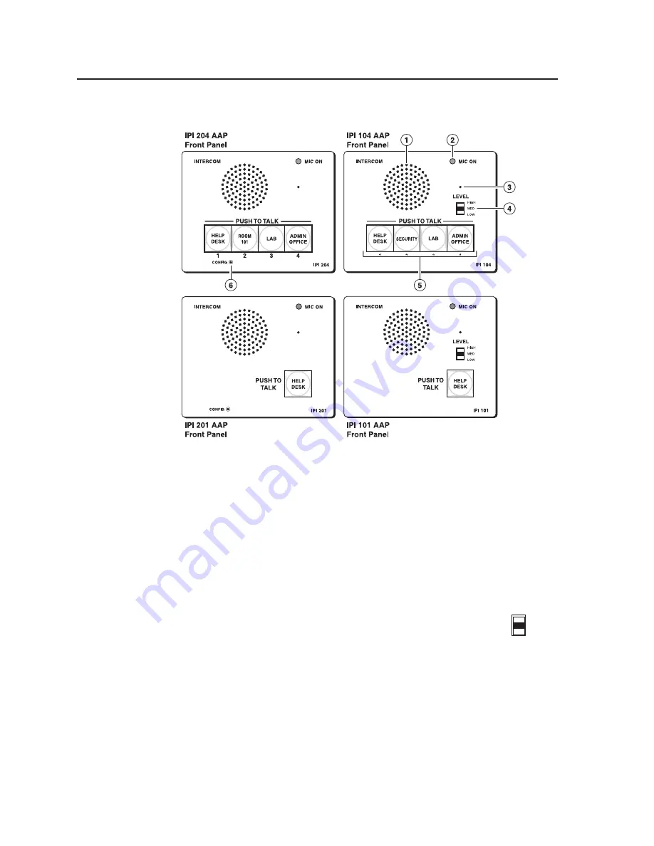
a


Speaker

 — This integrated speaker provides mono output at the IPI panel.  

b


Mic On LED

 — This LED lights under two circumstances:

•  When a configured Push to Talk button is pressed.  
•  To indicate that someone at the help desk console is listening and that the 

intercom is in monitoring mode.  Monitoring mode permits hands‑free 

operation: the user does not have to press the Push to Talk button to speak into 

the intercom.  It also lets help desk staff monitor what is happening to 

determine whether to send security personnel to that room.

c


Microphone

 — Push one of the butttons and talk.  The microphone is behind this 

opening.

d


Level switch

 — This three‑position switch lets you change the 

speaker’s loudness level (IPI 100 series, only).

e


Push to Talk button(s)

 — The IPI 101 AAP and IPI 201 units include 

one of these buttons, and the IPI 104 AAP and IPI 204 units have 

four.

N

  The MLC and IPI intercoms must be configured (via software) to associate 

each button with the IP address of a specific console PC or intercoms.  Once 
configured, the IPI 101 AAP and IPI 201 can communicate to one location (one 
IP address).  The IPI 104 AAP and IPI 204 can communicate with up to four 
different locations.

f


Config Port (IPI 200 Series only)

 — This 2.5 mm port is used to configure the 

IPI 201 and IPI 204 and to upload firmware when necessary.

LEVEL

HIGH

MED

LOW

Summary of Contents for IPI 101 AAP

Page 1: ...C ON LEVEL HIGH MED LOW IPI 101 PUSH TO TALK HELP DESK INTERCOM MIC ON LEVEL HIGH MED LOW IPI 104 PUSH TO TALK 1 2 3 4 SECURITY LAB ADMIN OFFICE HELP DESK INTERCOM MIC ON IPI 201 PUSH TO TALK HELP DES...

Page 2: ...m machen da im Inneren des Geh uses dieses Produktes gef hrliche Spannungen die nicht isoliert sind und die einen elektrischen Schock verursachen k nnen herrschen Achtung Lesen der Anleitungen Bevor S...

Page 3: ...ction against harmful interference when the equipment is operated in a commercial environment This equipment generates uses and can radiate radio frequency energy and if not installed and used in acco...

Page 4: ......

Page 5: ...ions 2 5 Single PC to panel 2 5 Multiple PCs to panel 2 6 Panel to panel mode 2 7 Server mode 2 8 Intercom with amplifier 2 9 Chapter Three Operation 3 1 Front Panel Features and Operation 3 2 Button...

Page 6: ...ents 5 12 Call forwarding 5 13 Setting up a peer to peer network 5 13 Setting up one PC as a server 5 14 Appendix A Specifications Part Numbers Accessories A 1 Specifications IPI 100 Series A 2 Includ...

Page 7: ...respective owners Appendix C Mounting C 1 Mounting the IPI 100 Series C 2 Mounting the IPI 200 Series C 3 Appendix D Button Labels D 1 Installing or Replacing Button Labels D 2 Button Label Generator...

Page 8: ...Table of Contents cont d IPI 100 and IPI 200 Series Table of Contents iv...

Page 9: ...IPI 100 and IPI 200 Series 1 Chapter One Before you get Started About This Manual About the IP Intercom Modules Features System Requirements UL Requirements...

Page 10: ...and is connected to one or more IPI Intercom Systems MLC 226 IP with IPI 104 101 AAP or stand alone IPI 201 204 AAP or 2 gang models via a local area network MLC refers to an MLC 226 IP MediaLink Con...

Page 11: ...AP N The IPI 201 and IPI 204 are stand alone units that do not require a connection to a MediaLink controller Connections between the IPI 101 AAP and IPI 104 AAP intercoms with MLC 226 IP and the netw...

Page 12: ...quipment for each room GlobalViewer software can be configured to automatically notify a help desk operator or security personnel via e mail Help desk operators or other authorized personnel can then...

Page 13: ...B ADMIN OFFICE HELP DESK CONFIG IPI 204 Extron INTERCOM MIC ON IPI 204 PUSH TO TALK 1 2 3 4 ROOM 101 LAB ADMIN OFFICE HELP DESK CONFIG INTERCOM MIC ON IPI 201 PUSH TO TALK HELP DESK CONFIG IPI 201 Ext...

Page 14: ...Preface cont d IPI 100 and IPI 200 Series Preface 1 6...

Page 15: ...IPI 100 and IPI 200 Series 2 Chapter Two Installation IPI Rear Panel Features and Cabling MLC Audio Connection Sample Applications...

Page 16: ...45 connectors into this port Plug the other end of the cable into the Intercom connector on the MLC 226 IP s rear panel as shown in the following figure HOST CONTROL R 1 DIGITAL I O 2 Tx 3 Rx 5 GND 3...

Page 17: ...apply only to the IPI 201 and IPI 204 models c Power Connect a cable between the 2 pole 3 5 mm captive screw connector and a 12 VDC 1 A power supply included C The power supply shall not be permanentl...

Page 18: ...can be connected to local powered speakers or to any audio or paging system See the wiring guide in the illustration below MLC 226 IP Rear Panel MLC 226 IP Rear Panel R INTERCOM AUDIO OUT To from the...

Page 19: ...ME CONFIG IR ON OFF AUTO IMAGE MUTE LAPTOP VCR DVD AUX VIDEO PC MLC 226 IP Help Desk Console IP 10 XX XX 01 Audio Card INTERCOM MIC ON LEVEL HIGH MED LOW IPI 104 PUSH TO TALK 1 2 3 4 SECURITY LAB ADMI...

Page 20: ...rding is used Extron recommends that no more than six PCs should be set up for call forwarding See chapter 5 for instructions on how to install and use the software 2 Connect up to a maximum of 250 in...

Page 21: ...VIDEO PC MLC 226 IP INTERCOM MIC ON LEVEL HIGH MED LOW IPI 101 PUSH TO TALK HELP DESK Lab IP 10 XX XX 03 Straight through Network Cable MLC 226 IP AAP IPI 101 AAP PROJECTOR 1 2 3 4 5 6 VOLUME CONFIG I...

Page 22: ...VCR DVD AUX VIDEO PC Classroom IP 10 XX XX 05 MLC 226 IP AAP IPI 101 AAP PROJECTOR 1 2 3 4 5 6 VOLUME CONFIG IR ON OFF AUTO IMAGE MUTE LAPTOP VCR DVD AUX VIDEO PC MLC 226 IP INTERCOM MONITOR LEVEL HIG...

Page 23: ...NOT GROUND OR SHORT SPEAKER OUTPUTS INPUTS L R L R REMOTE VOL MUTE 10V 50mA L MPA 152 R C US LISTED 17TT AUDIO VIDEO APPARATUS SI 3CT LP Ceiling Speakers POWER RELAY C NO AUDIO OUT LAN 2 Power on the...

Page 24: ...Installation cont d IPI 100 and IPI 200 Series Installation 2 10...

Page 25: ...IPI 100 and IPI 200 Series 3 Chapter Three Operation Front Panel Features and Operation Button Operation...

Page 26: ...hat room c Microphone Push one of the butttons and talk The microphone is behind this opening d Level switch This three position switch lets you change the speaker s loudness level IPI 100 series only...

Page 27: ...of amber Once a call is successfully connected press and hold the button when you speak and release it to allow the other party to speak N You must press and hold an IPI s button to speak and to call...

Page 28: ...IPI 100 and IPI 200 Series Operation 3 4 Operation...

Page 29: ...d IPI 200 Series 4 Chapter Four Initial Configuration Before you Begin Setting the IP Address by Global Configurator Setting the IP Address Using Embedded Web Pages Setting the IP Address Using the AR...

Page 30: ...IP address for your IPI 200 Series device from your A V system s network administrator 2 Write down the unit s MAC address a 12 digit number found on a label on the rear panel of the unit ex 00 05 A6...

Page 31: ...panel Config port at its factory default IP address To set an IP address with a GC project file open 1 From the Edit menu select Add Device The Add Device dialog box opens see the figure below 2 Selec...

Page 32: ...ox On Windows XP the TCP IP Properties dialog box is found at Start My Network Places right click to Properties Local Area Connection right click to Properties Internet Protocol TCP IP Properties 3 Re...

Page 33: ...er connection is immediately lost The device with its new IP address and subnet mask is now ready to be connected to your A V network To return the local PC to its original TCP IP settings 1 Close the...

Page 34: ...prompt window on a local PC On Windows XP a command prompt window can be found at Start All Programs Accessories Command Prompt 2 At the command prompt type arp s IP address MAC address example C arp...

Page 35: ...IPI 100 and IPI 200 Series 5 Chapter Five HelpDesk Software Introduction to the Software System Requirements Installing the Software Starting the Program Configuring the IPI Intercom System...

Page 36: ...subnets it is best to set up a dedicated VLAN If a firewall is required the following ports need to be open UDP port 3121 audio traffic TCP telnet port 23 control and status UDP port 3122 inter helpd...

Page 37: ...er or the Start menu to navigate to the IPI folder The program opens with the Getting Started pop up screen displayed Use the scrollbar to find basic information about Log in as User Log in as a HelpD...

Page 38: ...following section provides step by step procedures for some of the IP Intercom system s most common operations For details about operations not shown here the user should refer to the HelpDesk help fi...

Page 39: ...elp menu or press F1 from within the HelpDesk program Basic Configuration Using the Configuration Utility 1 In the Tools menu select Configuration Utility The first time the utility is used after open...

Page 40: ...updated using devices from the Global Configurator file 5 Go to Configuring an IP device with the configuration utility see page 5 8 Entering an IP address manually 1 2 3 4 1 Select Manually by IP Add...

Page 41: ...scans the local subnet for available intercoms 3 A Scan Progress dialog box opens indicating the progress of the scan 4 The scan detects only intercoms that are on the same local subnet and adds them...

Page 42: ...ct one of the IP devices in the Intercom List 2 When it is highlighted its information is displayed in the Selected Intercom pane 3 In the Selected Intercom pane the unit s Administrator Password and...

Page 43: ...alk button by clicking the Talk button and holding down the mouse button or by pressing and holding down the keyboard spacebar 3 Speak into the headset s microphone The Local Mic VU meter will oscilla...

Page 44: ...the Help Desk Preferences dialog box 2 If necessary select one of the IP devices on the Active Intercom List 3 Activate the Listen button The intercom button turns from low amber to high amber color t...

Page 45: ...cement button 3 The Group Selection pane becomes visible Groups that are available are listed in black text groups that are not available are grayed out Select an available group or All Intercoms 4 Th...

Page 46: ...ols menu select the Manage Sound Bites option 2 Click on the file button and go to C Program Files Extron IPI wav folder Select the wav files that you wish to be available 3 Click OK to close the Mana...

Page 47: ...desk PC 2 All intercoms must be linked to the IP address of one of the available help desks a Open the Configuration Utility and select an intercom in the intercom list b In the Button IP assignments...

Page 48: ...d is step 1b onto the help desk PC 2 All intercoms must be linked to the server s IP address a Select an intercom in the intercom list b In the Button IP assignments pane enter the server PC s IP addr...

Page 49: ...ies HelpDesk Software 5 The server PC must be set to Server Mode a Under the Tools menu click on Preferences The Preferences box opens b Click the Forwarding tab c Check the Mode box d An OK button ap...

Page 50: ...HelpDesk Software cont d IPI 100 and IPI 200 Series HelpDesk Software 5 16 e Exit and restart the program When the program restarts the window will have changed...

Page 51: ...A Appendix A Specifications Part Numbers Accessories Specifications IPI 100 Series Included Parts IPI 100 Series Accessories IPI 100 Series Specifications IPI 200 Series Included Parts IPI 200 Series...

Page 52: ...5 mm captive screw connector 2 pole Amplified speaker IPI 300 mW continuous 1 THD Ethernet control interface via MLC 226 IP Ethernet control communications port 1 female RJ 45 connector Ethernet data...

Page 53: ...out notice Included Parts IPI 100 Series These items are included in each order for an IPI intercom module Included parts Replacement part number IPI 104 AAP black white 70 502 0x IPI 101 AAP black wh...

Page 54: ...output port 1 via IPI speaker Line level output 10 dBV 316 mVrms balanced unbalanced via 3 5 mm captive screw connector 3 pole Amplified speaker output 300 mW continuous 1 THD Ethernet control interfa...

Page 55: ...nt Yes furniture and wall mountable with optional faceplate and mounting kits Enclosure type Metal faceplate Enclosure dimensions IPI 201 IPI 204 faceplate 4 5 H x 4 6 W x 0 1 D 11 4 cm H x 11 7 cm W...

Page 56: ...04 Rear IPI 204 AAP Rear Product weight 0 5 lbs 0 2 kg Shipping weight 3 lbs 1 kg Vibration ISTA 1A in carton International Safe Transit Association Regulatory compliance Safety CE c UL UL EMI EMC CE...

Page 57: ...white 60 809 0x IPI 204 AAP black white 60 810 1x IPI 204 2 gang black white 60 810 0x 12 V 1 A power supply 70 055 01 Button labels 33 1344 01 IPI 200 Series Installation Instructions Accessories IPI...

Page 58: ...Specifications Part Numbers Accessories cont d IPI 100 and IPI 200 Series Specifications Part Numbers Accessories A 8...

Page 59: ...IPI 100 and IPI 200 Series B Appendix B SIS Programming and Control Introduction to SIS Symbols used in this manual Error messages Command Response table for SIS commands...

Page 60: ...one or more characters per field No special characters are required to begin or end a command sequence When the IPI determines that a command is valid it executes the command and sends a response to...

Page 61: ...sponse to the host device If the IPI is unable to execute the command because the command is invalid or it contains invalid parameters it returns an error response to the host The error response codes...

Page 62: ...or Telnet or RS 232 command codes the corresponding URL uniform resource locator encoded for Web browsers command codes the IPI s responses to the host and a description of the command s function or t...

Page 63: ...s CR LF carriage return line feed hex 0D 0A Carriage return no line feed hex 0D use the pipe character instead for URL encoded commands Space character Pipe vertical bar character E Escape key hex 1B...

Page 64: ...me as for setting a value For example for E CN the response is Ipn X1 rather than just the data X3 Password minimum length 4 characters maximum length 12 characters no special characters are allowed N...

Page 65: ...s converted into single 16 bit decimal number X7 Hardware MAC address 8 least significant hex nibbles converted into single 32 bit decimal number N This could be as large as 10 digits X20 Voltage in v...

Page 66: ...nit because the relay is pulsed During a pulse the relay is toggled to its opposite state and then back to the original state View the relay state 1O 1O Rly 1 X Front panel security lockout modes exec...

Page 67: ...d and current versions of firmware Example 0Q 0Q 1 03 1 00 1 18 IPI 201 IPI 204 Thu 20 Jan 2005 09 41 47 GMT 1 01 1 31 IPI 201 IPI 204 Tue 14 Jun 2005 00 54 58 GMT Query bootstrap firmware version 2Q...

Page 68: ...characters and the minus sign The first character must be a letter the last character cannot be a minus sign hyphen Case does not matter Set unit name to factory default24 E CN W 20CN Ipn X4 X4 the fa...

Page 69: ...ns responses are not echoed to the host 1 verbose mode is on default for RS 232 host control responses are echoed to the host and displayed to the user 2 send tagged responses for queries 3 verbose mo...

Page 70: ...me effective in kernel versions 1 53 or higher Get connections listing ECC WCC verbose modes 0 1 of connections verbose modes 0 1 Icc of connections Password and security settings Set administrator pa...

Page 71: ...er Setting two ports to the same number could cause networking conflicts and will also result in an E13 invalid parameter error N If you remap a port you must set the port number to 1024 or higher unl...

Page 72: ...nside the custompages directory In example 3 the user moved to a directory called oak Change back to the root directory E CJ W 2F CJ Dir Moves to the system s root directory Go up one directory level...

Page 73: ...by the delimited data to be written to the flash file memory Retreive file from user flash memory Send a page GET on port 80 followed by WSF e g http 192 168 254 254 mypage html cmd WSF Responds with...

Page 74: ...f upload GMT file size 2 in bytes file 3 filename 3 day date time3 of upload GMT file size 3 in bytes file n filename n day date timen of upload GMT file size n in bytes file n 1 space remaining to 7...

Page 75: ...ser files in flash memory will not be deleted Reset all device settings and delete files EZY WZY Zpy N This is an absolute system reset but excludes IP settings such as IP address subnet mask gateway...

Page 76: ...SIS Programming and Control cont d IPI 100 and IPI 200 Series SIS Programming and Control B 18...

Page 77: ...IPI 100 and IPI 200 Series C Appendix C Mounting Mounting the IPI 100 Series Mounting the IPI 200 Series...

Page 78: ...nuts as shown below Extron PROJECTOR MLC 226 IP AAP 1 2 3 4 5 6 VOLUME CONFIG IR PC AUX VIDEO DVD VCR DOC CAM LAPTOP AUTO IMAGE MUTE ON OFF Extron MLC 226 IP AAP MediaLink Controller Extron IPI 104 A...

Page 79: ...f the intercom after it has been inserted through the front of the AAP plate Extron IPI 204 AAP Intercom rear view Clamp Bracket included 1 Before cables are attached insert the IPI through the front...

Page 80: ...Mounting cont d IPI 100 and IPI 200 Series Mounting C 4...

Page 81: ...IPI 100 and IPI 200 Series D Appendix D Button Labels Installing or Replacing Button Labels...

Page 82: ...e the buttons You can create labels with names alphanumeric characters or color graphics for easy and intuitive input and output selection Installing the Button Label Generator software The Extron But...

Page 83: ...ndow opens 2 In the Systems selection box choose the IPI 101 201 or the IPI 104 204 option to match the button label size and quantities for your TouchLink panel 3 Using standard Windows controls you...

Page 84: ...cap and the diffuser as shown in the figure at right Using a rotating motion of the screwdriver see the figure at right carefully pry the two pieces apart 3 Replace the label with the new button labe...

Page 85: ...mirates Dubai This Limited Warranty does not apply if the fault has been caused by misuse improper handling care electrical or mechanical abuse abnormal operating conditions or non Extron authorized m...

Page 86: ...226 IP into the wall box es or furniture see page C 2 Ensure the HelpDesk PC s is connected to the network and power it on Configure the MLC s as described in the MLC 226 IP User s Manual and the Glo...

Reviews: